Steam-liquid-solid three-phase energy accumulator

A three-phase energy storage tank and accumulator technology, applied in the field of energy storage, can solve the problems of imbalance, inability to fully utilize the energy storage potential of the solution, and concentration difference limitation, and achieve the improvement of energy storage density, volume reduction, and simple control. Effect

Active Publication Date: 2015-03-11
BEIJING UNIV OF TECH
View PDF6 Cites 2 Cited by
  • Summary
  • Abstract
  • Description
  • Claims
  • Application Information

AI Technical Summary

Problems solved by technology

However, in order to avoid the danger of solution crystallization in the current solution absorption energy storage, the concentration difference before and after the working solution energy storage is limited, and the energy storage potential of the solution cannot be fully utilized. In order to further tap the potential of solution energy storage and improve solution energy storage The energy storage density of the device, invented a vapor-liquid-solid three-phase accumulator using the absorption refrigeration working medium as the energy storage medium, and this accumulator can be directly combined with the absorption refrigeration and air conditioning system to form an energy storage type Air-conditioning system to solve the imbalance between energy supply and air-conditioning energy consumption

Method used


Image

  • Steam-liquid-solid three-phase energy accumulator
  • Steam-liquid-solid three-phase energy accumulator

Examples


Embodiment Construction

[0016] The patent of the present invention will be further described below in conjunction with the drawings.

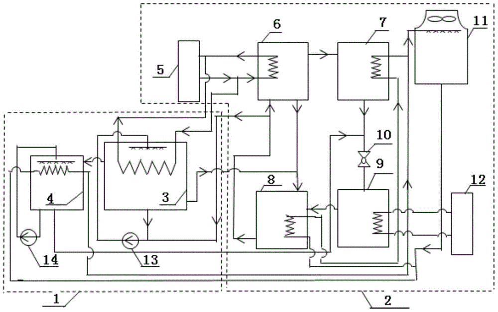
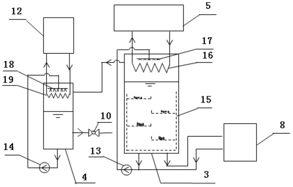
[0017] See figure 1 with figure 2 , The three-phase accumulator 1 includes a three-phase accumulator tank 3 and a liquid refrigerant accumulator tank 4. When accumulating energy, the three-phase accumulator 1 stores the excess heat of the heat source 5 in the three-phase accumulator 1. The heat source 5 directly provides heat to the three-phase accumulator tank 3, using the porous surface in the three-phase accumulator tank 3. The tube heat exchanger 16 heats the energy storage medium and relies on the solution spray pump 13 to pressurize and the solution nozzle 17 to spray during the heating process. The solution is heated and concentrated until crystals are produced, and the crystals are distributed in the crystal distributor 15 The refrigerant vapor generated by heating enters the liquid refrigerant storage tank 4 (for example, when the lithium bromide-water solutio...


PUM


Abstract

The invention provides a steam-liquid-solid three-phase energy accumulator, and belongs to the technical field of energy accumulation. The steam-liquid-solid three-phase energy accumulator uses an absorption type refrigeration work medium as an energy accumulation medium, a three-phase energy accumulation tank and a liquid stage refrigerant accumulation tank are organically combined for forming the steam-liquid-solid three-phase energy accumulator, the two accumulation tanks respectively adopt the upper part heat exchange and lower part liquid storage integration and liquid self circulation spraying design, an upper part heat exchanger of the three-phase energy accumulator adopts a surface porous pipe heat exchanger for reinforcing the heat mass transfer process, the solution crystallization and crystal dissolution are accelerated through the arrangement of a crystal distributor at the lower part of the three-phase energy accumulation tank, and four layers of filter screen devices are arranged and are ranged in a staggered way in different layers. The steam-liquid-solid three-phase energy accumulator has the advantages that the danger caused by crystallization in the existing solution absorption type energy accumulation is avoided, meanwhile, the energy accumulation density is obviously improved through being compared with that of a three-phase energy accumulation mode, the energy accumulation density can be improved by more than 50 percent through the 50-percent crystallization rate, in other words, the 50-percent crystallization rate is realized, the size of the energy accumulator is reduced by more than a half, the regulation and the control are simple, the steam-liquid-solid three-phase energy accumulator is combined with a traditional absorption type refrigeration air conditioner system for forming an absorption type refrigeration air conditioner system with the three-phase energy accumulator.

Description

Technical field [0001] The invention belongs to the technical field of energy storage, and particularly relates to a vapor-liquid-solid three-phase accumulator based on the absorption principle. Background technique [0002] Energy storage technology is one of the important measures to solve the unsynchronization and mismatch of supply and demand in all aspects of energy production, transportation and use. The periodicity, intermittent, unstable and unmatched nature of renewable energy such as solar energy With the characteristics of low heat flux, energy storage technology plays a vital role in its efficient utilization. Among various energy storage technologies, sensible heat and latent heat storage are relatively mature and widely used energy storage technologies. However, the main disadvantage of the former is its low energy storage density, while the latter has a large heat transfer temperature difference, energy storage and energy release rate. low. The chemical solution ...

Claims


Application Information

Patent Timeline
Patent Type & Authority Applications(China)
IPC IPC(8): F25B27/00F25B15/00
CPCF24F5/0014F25B15/00F25B43/003F25B41/30Y02B30/62Y02A30/27
Inventor 毕月虹
Owner BEIJING UNIV OF TECH
Why Eureka
Try Eureka