Exhaust gas denitration equipment for reciprocating engine
An engine, reciprocating technology, applied in the direction of mechanical equipment, engine components, combustion engines, etc., can solve the problems of turbocharger output reduction, turbocharger response deterioration, turbo hysteresis, etc., to prevent deterioration and prevent temperature drop Effect
- Summary
- Abstract
- Description
- Claims
- Application Information
AI Technical Summary
Problems solved by technology
Method used
Image
Examples
Embodiment 1
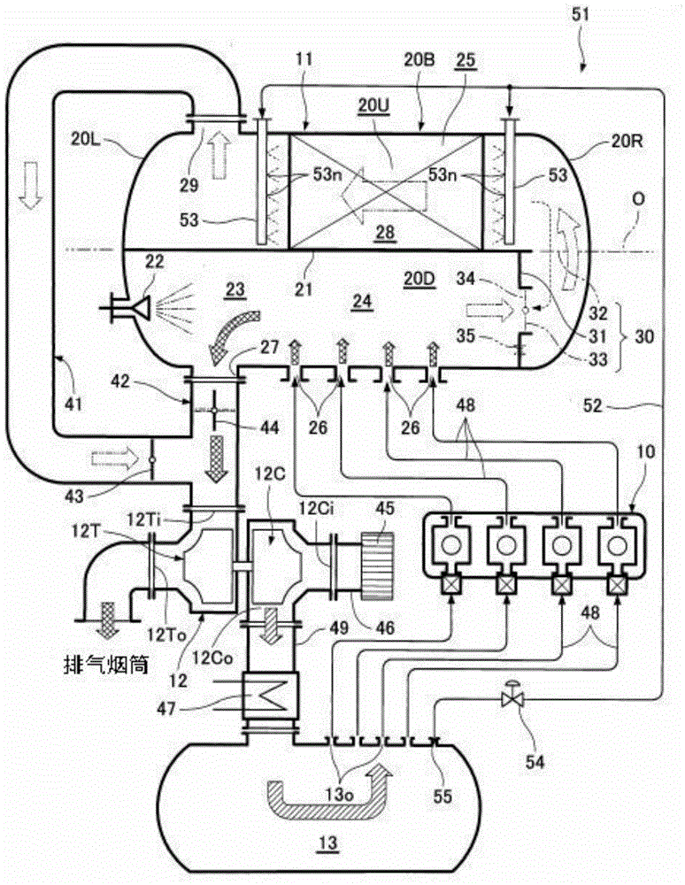
[0038] figure 1 Example 1 of, for example, an exhaust gas denitrification facility for a marine diesel engine is shown. This exhaust gas denitration device performs denitration treatment on exhaust gas discharged from the combustion chamber of the diesel engine 10 . 11 is a denitration reaction container, 12 is a supercharger driven by the exhaust gas discharged from the diesel engine 10, and 13 is a scavenging air storage that temporarily stores the combustion air compressed by the supercharger 12 and supplies it to the combustion chamber of the diesel engine 10. box.
[0039] The denitration reaction vessel 11 is formed as a pressure-resistant container provided with a horizontal cylindrical trunk portion 20B and pressure-resistant end plates 20R and 20L, and the pressure-resistant end plates 20R and 20L are attached to the ends of the trunk portion 20B. Both ends are curved and convex. In addition, the denitration reaction container 11 is divided into a lower space 20D a...
Embodiment 2
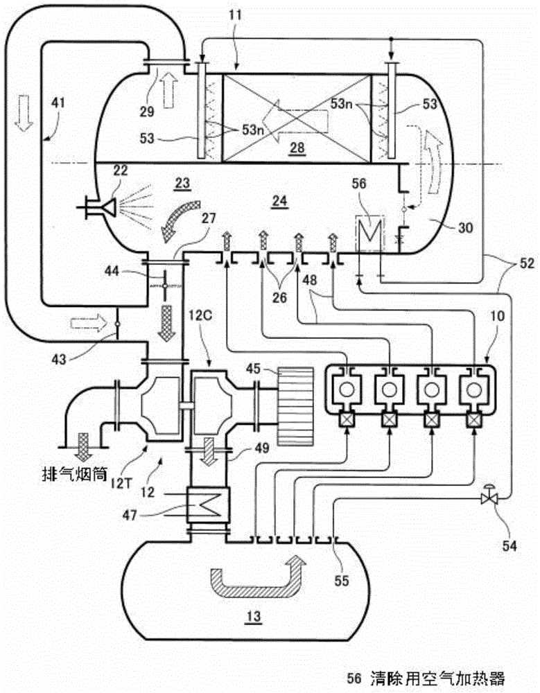
[0058] In Example 1, part of the combustion air in the scavenging air receiver 13 was used as purge air, but in Example 2, this purge air was heated and used. In addition, the same code|symbol is attached|subjected to the same component as Example 1, and description is abbreviate|omitted.
[0059] Example 2 as figure 2 As shown, in the waste gas storage tank 24 heated to 400-500° C. by the waste gas, a heat exchange type purge air heater 56 for raising the temperature of the purge air is installed.
[0060] That is, in the scavenging air storage tank 13, after sucking a part of the dry combustion air at 40 to 50° C. as the cleaning air into the cleaning air suction pipe 52, it is introduced into the cleaning air heater 56, and passes through the exhaust gas storage. The exhaust gas in the gas box 24 is heated to about 200°C. Then, the heated purge air is introduced from the purge air suction pipe 52 into the purge header 53 and sprayed from the spray nozzles 53n toward the ...
Embodiment 3
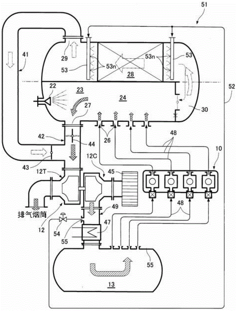
[0063] In Embodiment 1 and Embodiment 2, a part of the combustion air of the scavenging air receiver 13 is taken out as the purge air. Part of the combustion air is taken out. In addition, the same code|symbol is attached|subjected to the same component as Example 1, and description is abbreviate|omitted.
[0064] like image 3 As shown, in the supercharger discharge pipe (path) 49 , an air outlet 55 is provided on the upstream side of the intercooler 47 , and the purge air suction pipe 52 is connected to the air outlet 55 . In this way, part of the combustion air compressed by the compressor portion 12C of the supercharger 12 and cooled by the intercooler 47 is taken out from the air outlet 55 as purge air, thereby obtaining a temperature of about 200° C. (including entrainment air). Air for removal of moisture in the air). Here, the air pressure relative to the supercharger discharge pipe 49 is 0.4 MPaG, and the exhaust gas pressure in the reaction chamber 25 is as low as...
PUM
 Abstract
Description
Claims
Application Information
 - R&D Engineer
- R&D Manager
- IP Professional
- Industry Leading Data Capabilities
- Powerful AI technology
- Patent DNA Extraction
Browse by: Latest US Patents, China's latest patents, Technical Efficacy Thesaurus, Application Domain, Technology Topic, Popular Technical Reports.
© 2024 PatSnap. All rights reserved.Legal|Privacy policy|Modern Slavery Act Transparency Statement|Sitemap|About US| Contact US: help@patsnap.com


