Process station for a machine as well as control device and control method

A technology of a control device and a control method, applied in the field of processing stations, can solve the problems of increased processing costs, time-consuming, and high machine costs, and achieve the effects of reducing processing costs and reducing costs.

Active Publication Date: 2015-03-18
ROBERT BOSCH GMBH
View PDF9 Cites 2 Cited by
  • Summary
  • Abstract
  • Description
  • Claims
  • Application Information

AI Technical Summary

Problems solved by technology

[0004] This manipulation of the substrate requires many manipulation steps and is therefore time-consuming
As a result, processing costs increase
Also, since robots capable of movement in X, Y, Z and Θ directions are expensive, resulting in high cost of the machine itself
This also brings an increase in the processing cost of the machine

Method used


Image

  • Process station for a machine as well as control device and control method
  • Process station for a machine as well as control device and control method
  • Process station for a machine as well as control device and control method

Examples


Embodiment Construction

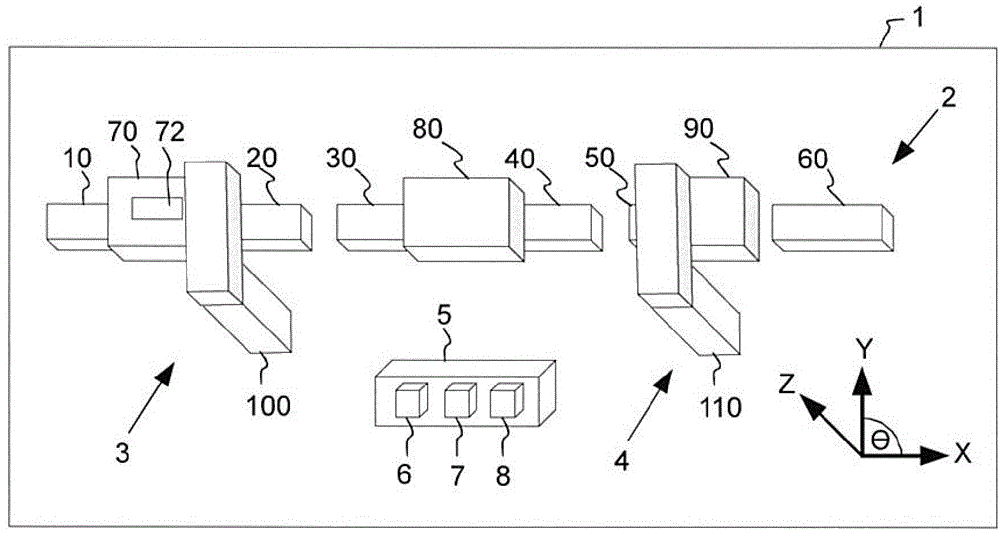
[0036] figure 1 Shown is a machine 1 for producing items such as semiconductor components or the like on a substrate such as a wafer. The machine 1 comprises a conveyor system 2 connecting a first processing station 3 and a second processing station 4 . The machine 1 also comprises a control device 5 having a first control unit 6 , a second control unit 7 and a third control unit 8 . Machine 1 may be a production line.

[0037] figure 1 The conveying system 2 in includes the first driving device 10, the second driving device 20, the third driving device 30, the fourth driving device 40, the fifth driving device 50, the sixth driving device 60, the first carrier 70, the second carrier 80 and a third carrier 90 , the first carrier 70 carries a load 72 (such as objects to be produced by the machine 1 , etc.). The first to third carriers 70 , 80 , 90 can be moved in the transport system 2 by magnetic force generated by the first to sixth drive devices 10 , 20 , 30 , 40 , 50 , ...


PUM


Abstract

A process station (3, 4) for a machine (1) as well as a control device (5) and a control method for controlling a movement in a process of a machine (1) are provided. The process station (3, 4) comprises a robot (100, 110) for handling a load (72) being conveyed by a carrier (70, 80, 90) movable by magnetic force in a specific conveying direction of a conveying system (2), wherein the robot (100, 110) is controllable by a control unit (6) to move in a moving direction different from the specific conveying direction of the conveying system to handle the load (72), and wherein the specific conveying direction for conveying the load (72) and the moving direction of the robot (100, 110) are superimposed to handle the load (72) in the process station (3, 4) to eliminate a need for a movement of the robot (100, 110) in the conveying direction of the conveying system (2).

Description

technical field [0001] The invention relates to a processing station for a machine, and a control device and a control method for controlling movements in processing of a machine, wherein it is especially possible to eliminate the need for a pick-and-place robot to move in the conveying direction of a conveying system. Background technique [0002] In machines for the production of objects, conveyor systems are used to transport parts, tools, etc., which can be used for the production of objects, to different stations of the machine. For example, such a machine is described in US 4,096,821 which discloses a system for manufacturing thin film electronic devices on substrates. [0003] In such machines, usually the transfer system comprises a conveyor belt, which transfers the substrates one by one to the processing stations at the same speed. In the processing station, the substrate is removed from the belt, which is handled by a robot moving in the X, Y, Z and Θ directions,...

Claims


Application Information

Patent Timeline
Patent Type & Authority Applications(China)
IPC IPC(8): B65G54/02B65G47/90B65G43/00
CPCH01L21/67724H01L21/67709H01L21/67736B65G47/905B65G37/00Y10S901/07
Inventor M.哈林R.希布斯
Owner ROBERT BOSCH GMBH
Why Eureka
Try Eureka