Opaque white coating with non-conductive mirror

A mirror, transparent technology, applied in coatings, mirrors, electrical components, etc., can solve the problems of sensor reading errors and affect sensor performance, and achieve the effect of improving performance, reducing thickness, and low dielectric constant

A mirror, transparent technology, applied in coatings, mirrors, electrical components, etc., can solve the problems of sensor reading errors and affect sensor performance, and achieve the effect of improving performance, reducing thickness, and low dielectric constant

CN104422977AActive Publication Date: 2015-03-18APPLE INC

Image

  • Opaque white coating with non-conductive mirror
  • Opaque white coating with non-conductive mirror
  • Opaque white coating with non-conductive mirror

Examples


Embodiment Construction

[0023] The present disclosure can be understood by referring to the following detailed description when taken in conjunction with the accompanying drawings as described below. It should be noted that, for clarity of illustration, some of the elements in the various figures may not be drawn to scale, may be represented schematically or conceptually, or otherwise may not correspond exactly to certain physical configurations of the embodiments.

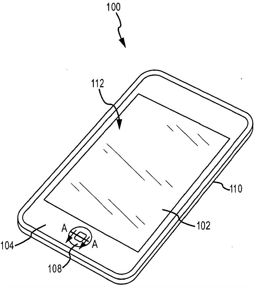
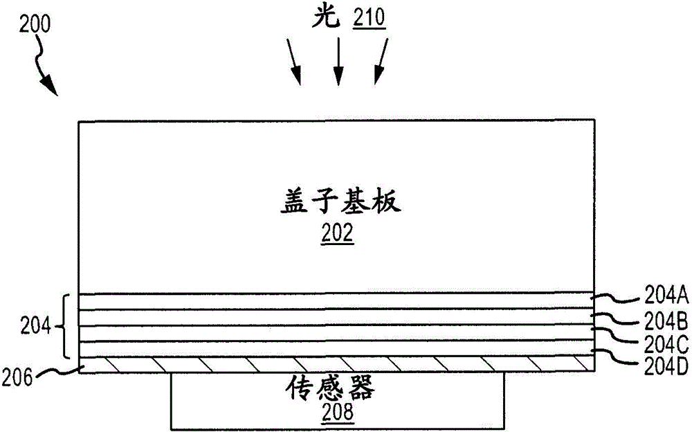
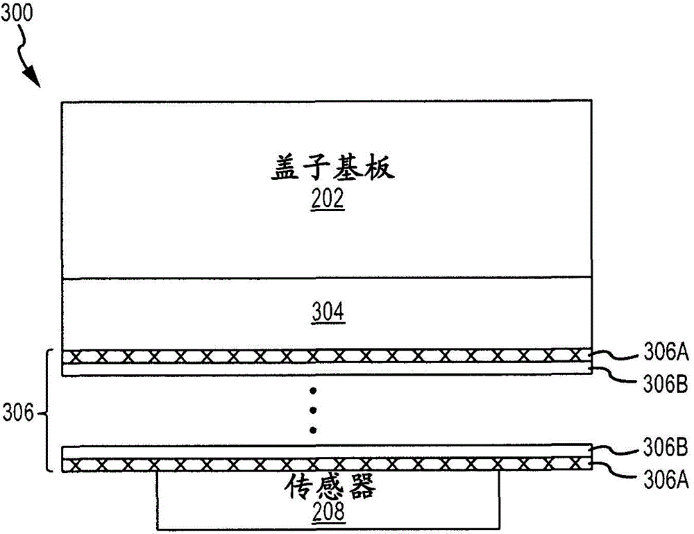
[0024] The disclosure provides a mirror structure between the white ink or coating and a highly sensitive sensor, such as a capacitive sensor. A layer of white ink may underlie a glass or sapphire upper surface, such as a cover glass, and may hide the capacitive sensor from view. The white ink layer may include white pigments such as titanium oxide (TiO 2 ). Mirror structures can include silicon oxide (SiO 2 ) layer with niobium pentoxide (Nb 2 o 5 ) first stack of interleaved layers. with TiO 2 Compared to SiO 2 and Nb 2 o 5 H...


PUM

PropertyMeasurementUnit
thicknessaaaaaaaaaa
thicknessaaaaaaaaaa
thicknessaaaaaaaaaa

Abstract

An opaque cover is provided for a capacitive sensor. The cover includes a transparent substrate, and at least one white coating layer including white pigments disposed over at least one portion of the transparent substrate. The cover also includes a non-conductive minor structure disposed over the at least one white coating layer. The non-conductive minor structure includes a number of first dielectric layers having a first refractive index interleaved with second dielectric layers having a second refractive index. The first and second dielectric layers have dielectric constants below a threshold.

Description

technical field [0001] Embodiments described herein generally relate to electronic devices having a non-conductive white coating stack that is both thin and opaque. More specifically, embodiments relate to electronic devices incorporating a thin, opaque white coating stack with a non-conductive mirror layer. Background technique [0002] Many portable digital devices incorporate at least one display screen to provide graphical information to a user or viewer. The display screen may include a liquid crystal display (LCD). Such devices may also include one or more sensors located under a cover glass that overlies the LCD and typically extends beyond the LCD. As an example, these sensors may be capacitive sensors. [0003] The device may also incorporate an opaque area, such as a white-coated area, outside the display screen (eg, outside the active display area) but under the cover glass. Opaque areas can include opaque ink like white ink underneath the cover glass or sapph...

Claims


Application Information

Patent Timeline
18 Mar 2015
Publication
CN104422977A
IPC
G02B5/08; G02B1/00
CPC
G02B1/10; C03C17/36; C03C17/3417; G02B5/003; G06F3/044; G02B5/26; C03C2217/42; C03C17/3639
Inventors
松雪直人; D·J·韦伯