High-precision deep hole combination drill and machining method thereof

A processing method and technology of compound drilling, applied in boring/drilling, metal processing equipment, drilling/drilling equipment, etc., can solve the problems of cumbersome operation, difficult size control, poor fatigue resistance in the processing process, etc. Processing cycle, reducing processing difficulty, and solving the effect of poor fatigue resistance

Active Publication Date: 2015-03-25
贵州凯星液力传动机械有限公司
View PDF9 Cites 3 Cited by
  • Summary
  • Abstract
  • Description
  • Claims
  • Application Information

AI Technical Summary

Problems solved by technology

[0004] The present invention aims to provide a high-precision deep-hole composite drill and its processing method to solve the existing problems of the existing deep-hole drills, such as poor drill bit fatigue resistance, difficult size control, easy wear, poor cooling effect, cumbersome operation and low efficiency in the processing process. Problems of low cost, long period and high cost

Method used


Image

  • High-precision deep hole combination drill and machining method thereof
  • High-precision deep hole combination drill and machining method thereof
  • High-precision deep hole combination drill and machining method thereof

Examples


Embodiment 1

[0040] The processing method of the above-mentioned high-precision deep hole compound drill is as follows:

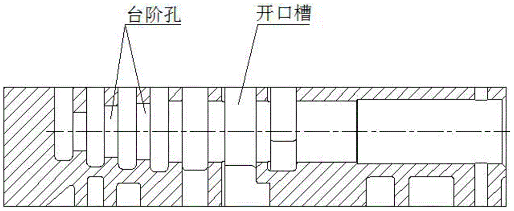
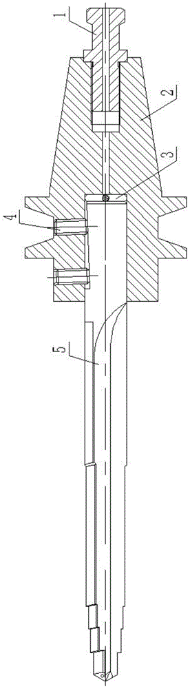
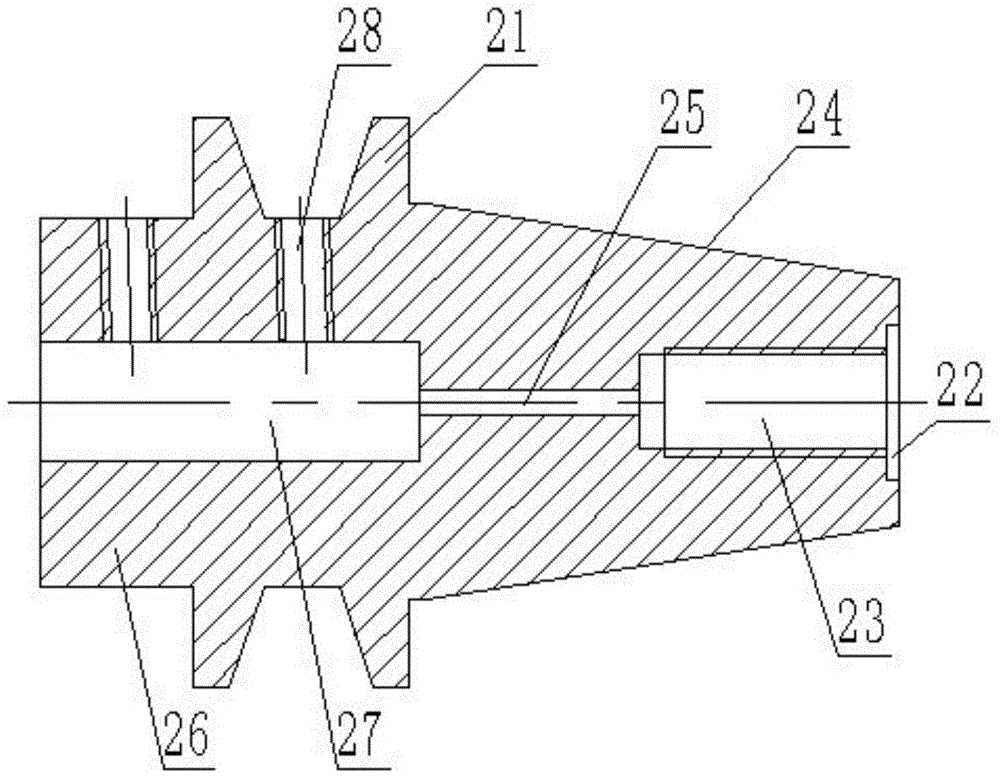
[0041]After the heat treatment, the knife handle 2 is machined with a precision numerical control lathe to produce a flange 21, a mounting hole 27, a pressing hole 28, a through hole 25, a connecting hole 23, a counterbore 22 and a tapered section 24, wherein the tapered section 24 remains The unilateral margin is 0.08mm, and then it is ground with a precision cylindrical grinder to ensure that the fit of the tapered section 24 after being tightened in the machine tool spindle reaches 85%; the straight groove drill 5 uses a standard hard alloy round The area bar is used as the blank, the liquid hole 55 is processed by laser ablation, and the remaining dimensions are ground by a precision cylindrical grinder and a universal CNC tool grinder. Among them, the radial dimension of the cutting edge 51 has a margin of 0.02mm on both sides; high precision After the deep hole co...

Embodiment 2

[0043] The processing method of the above-mentioned high-precision deep hole compound drill is as follows:

[0044] After the heat treatment, the knife handle 2 is machined with a precision numerical control lathe to produce a flange 21, a mounting hole 27, a pressing hole 28, a through hole 25, a connecting hole 23, a counterbore 22 and a tapered section 24, wherein the tapered section 24 remains The unilateral margin is 0.09mm, and then it is ground with a precision cylindrical grinder to ensure that the fit of the tapered section 24 after being tightened in the machine tool spindle reaches 83%; the straight groove drill 5 uses a standard hard alloy round The area bar is used as the blank, the liquid hole 55 is processed by laser ablation, and the remaining dimensions are ground by a precision cylindrical grinder and a universal CNC tool grinder. Among them, the radial dimension of the cutting edge 51 has a margin of 0.03mm on both sides; high precision After the deep hole c...

Embodiment 3

[0046] The processing method of the above-mentioned high-precision deep hole compound drill is as follows:

[0047] After the heat treatment, the knife handle 2 is machined with a precision numerical control lathe to produce a flange 21, a mounting hole 27, a pressing hole 28, a through hole 25, a connecting hole 23, a counterbore 22 and a tapered section 24, wherein the tapered section 24 remains The unilateral margin is 0.10mm, and then it is ground with a precision cylindrical grinder to ensure that the fit of the tapered section 24 after being tightened in the machine tool spindle reaches 89%; the straight groove drill 5 uses a standard hard alloy round The area bar is used as the blank, the liquid hole 55 is processed by laser ablation, and the remaining dimensions are ground by a precision cylindrical grinder and a universal CNC tool grinder. Among them, the radial dimension of the cutting edge 51 has a margin of 0.04mm on both sides; high precision After the deep hole c...


PUM

PropertyMeasurementUnit
diameteraaaaaaaaaa

Abstract

The invention discloses a high-precision deep hole combination drill which comprises a cutter handle, a blind rivet and a straight fluted drill. The front end of the blind rivet is inserted into a connecting hole in the right end of the cutter handle, and the straight fluted drill is inserted into a mounting hole formed in the left end of the cutter handle and is fixed by a compression screw and a compression groove. The invention further discloses a machining method of the high-precision deep hole combination drill. The machining method specifically comprises the steps of cutter handle machining, straight fluted drill finish machining, cutter handle finish machining, boundary dimension finish machining and dynamic balancing. The combination drill machined through the machining method has the advantages of being high in fatigue durability, high in strength, high in precision, resistant to abrasion, high in chip removal and cooling capacity, high in machining precision and the like, and the number of defective products or waste products can be greatly reduced.

Description

technical field [0001] The invention relates to the technical field of mechanical processing, in particular to a deep hole processing device and processing method, in particular to a high-precision deep hole compound drill and a processing method thereof. Background technique [0002] When processing parts in machinery factories, drilling processing accounts for 30%-40% of the total processing. With the advancement of science and technology, the requirements for dimensional accuracy and surface finish of mechanical product parts are increasing day by day. The processing of precision holes is often the key to production. Nowadays, spare parts in many industries need to process large and deep holes. During the processing, the tool holder is limited by the diameter of the hole, and the diameter is small, which relatively causes poor rigidity and low strength, which seriously affects the product. Quality, in addition, it is difficult to remove chips in large hole and deep hole m...

Claims


Application Information

Patent Timeline
Patent Type & Authority Applications(China)
IPC IPC(8): B23B41/02B23B35/00
CPCB23B31/005B23B51/00B23B51/12B23P15/28
Inventor 郑德猛胡志宇
Owner 贵州凯星液力传动机械有限公司
Why Eureka
Try Eureka