
Pulse laser zoom irradiation device

A pulsed laser, irradiation device technology, applied in optics, optical components, nonlinear optics, etc., can solve problems such as waveform distortion and energy loss

Inactive Publication Date: 2015-03-25
NORTHWEST INST OF NUCLEAR TECH
View PDF2 Cites 2 Cited by
  • Summary
  • Abstract
  • Description
  • Claims
  • Application Information

AI Technical Summary

Problems solved by technology

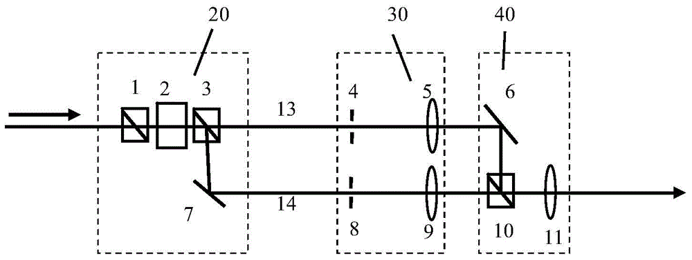
[0006] The present invention proposes a method based on an electro-optical clipping switch to directly split beams and cut pulse waveforms, while ensuring that the total optical length of each sub-optical path is equal to solve the problems of energy loss and waveform distortion caused by the process of beam splitting and cutting waveforms. Realize two-step zoom irradiation with only one set of electro-optic clipping switches

Method used


Image

  • Pulse laser zoom irradiation device
  • Pulse laser zoom irradiation device

Examples


Embodiment Construction

[0026] The zoom irradiation of pulsed laser is to realize the irradiation that the focal spot size changes within a laser pulse time, such as figure 2 shown. Its core is to make different positions of an optical pulse have different wavefronts, so that the focal spot changes with time when focusing, which generally requires three parts: optical pulse splitting and splitting, creating holes for the split optical pulses and Image transmission, light pulse combination and imaging.

[0027] The basic concept of the present invention is: in view of the segmentation of the optical pulse waveform needs to use the electro-optic clipping switch (i.e. the Pocekels box and the polarizer and the polarizer in the document "Review of Scientific Instruments, 2013, 84, 013509"), that is The "polarizer-electro-optic crystal-analyzer" structure can directly use the analyzer prism as a beam splitter, and at the same time realize the beam splitting and division of the light pulse, so that the i...


PUM


Abstract

The invention discloses a pulse laser zoom irradiation device. Beam splitting and waveform segmenting of optical pulse are simultaneously realized by directly using Glan prisms of electro-optical clipping switches, the fidelity of the optical pulse after beams are combined is guaranteed by adopting the aplanatic optical path design, and the change of focal spots is realized by using lenses with equal focal lengths and object hole diaphragms with different sizes. Compared with a conventional device, the pulse laser zoom irradiation device has the advantages that less electro-optical clipping switches are used, so that the utilization rate of incident light pulse energy is greatly improved; moreover, the device has extendibility, and multi-step light beam zoom irradiation can be obtained.

Description

technical field [0001] The invention relates to a laser irradiation device, in particular to an excimer laser zoom irradiation device whose light spot changes step by step with time in the nanosecond scale and is suitable for image transfer technology. Background technique [0002] Laser zoom irradiation can make the laser focal spot change rapidly with time in the same pulse time. Usually, the spot is enlarged first and then small within a pulse duration. In laser direct drive fusion, the laser focal spot can be made to implode the Shrink, thereby improving the coupling efficiency of the laser and the target. [0003] For excimer lasers, the zoom irradiation technology based on image transfer technology and electro-optical switch clipping proposed by Lehmberg et al. , the laboratory reported experiments related to zoom irradiation in 2013 (Kehne, et al., Review of Scientific Instruments, 2013.84(1):p.013509). The technology adopts the technical route of "beam splitting by...

Claims


Application Information

Patent Timeline
Patent Type & Authority Applications(China)
IPC IPC(8): G02F1/03G02B27/28
CPCG02F1/0311
Inventor 朱永祥赵学庆胡云王大辉张永生
Owner NORTHWEST INST OF NUCLEAR TECH
Learn More