Three-channel microwave rotary joint

A rotary joint, three-channel technology, used in waveguides, waveguide-type devices, electrical components, etc., can solve the problems of long effective signal transmission distance, signal interference, short service life, etc., and achieve precise control of bearing clearance and low loss. Broadband transmission, reduction in size and weight

Active Publication Date: 2015-03-25
BEIJING RES INST OF TELEMETRY +1
View PDF9 Cites 7 Cited by
  • Summary
  • Abstract
  • Description
  • Claims
  • Application Information

AI Technical Summary

Problems solved by technology

[0005] (1) Heavy weight: Since the weight of rotary joint products used on the ground is basically unlimited, and there are various forms, weight is less considered in design
[0006] (2) High transmission loss: When the signal is transmitted to the Ka frequency band, it is caused by the long effective transmission distance of the signal, poor transmission surface roughness and poor coupling matching of the choke slot;
[0007] (3) Large rotation fluctuation: due to the difference in coaxiality, one occurs in the part processing and assembly process, and the other is caused by thermal deformation in a complex space environment;
[0008] (4) Poor isolation: multi-channel rotary joints are mainly in the form of nesting, and physical isolation is not used between channels, resulting in poor isolation and interference between signals
[0009] (5) Short application life: the existing ordinary bearings of rotary joints are prone to low-temperature cold welding in the space environment of aerospace vehicles, which will cause the bearings to be stuck and the service life is very short

Method used


Image

  • Three-channel microwave rotary joint
  • Three-channel microwave rotary joint
  • Three-channel microwave rotary joint

Examples


Embodiment Construction

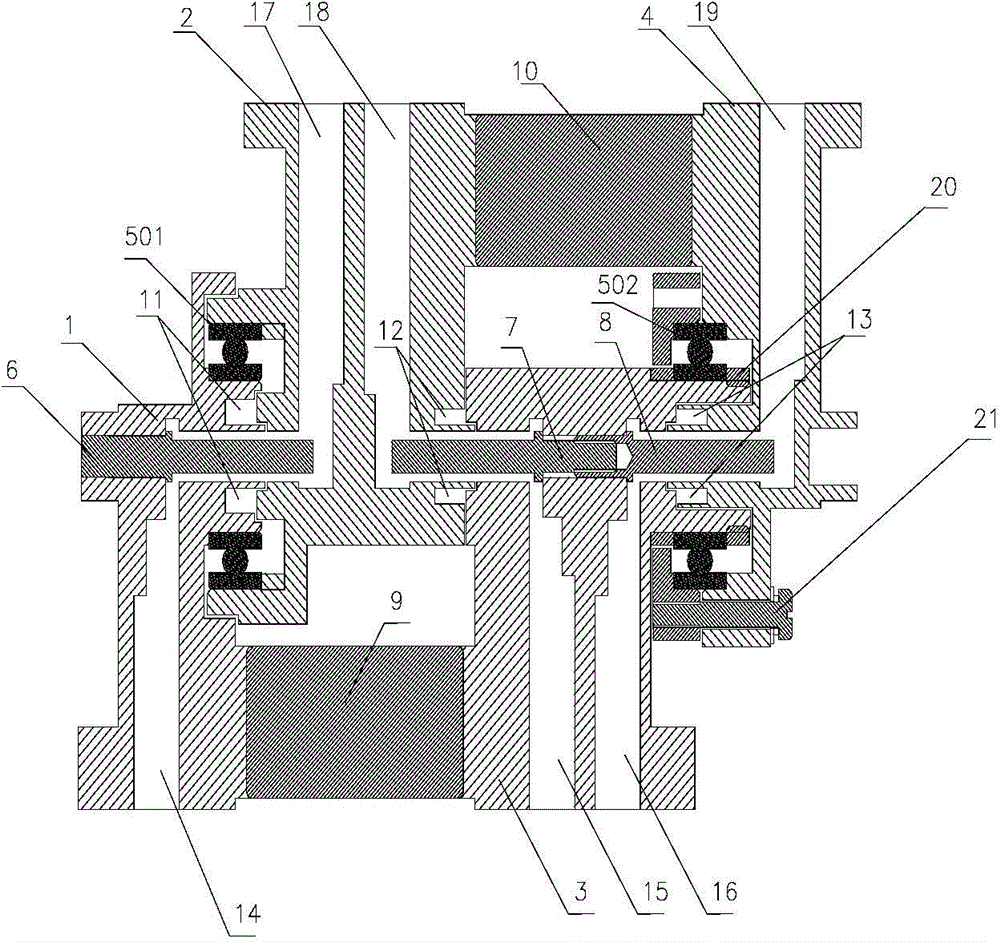
[0030] The invention relates to a three-channel low-loss microwave rotary joint combination, which can be especially applied to the satellite relay terminal subsystem self-tracking antenna system deployment axis, X-axis, Y-axis microwave receiving and transmitting channels, which can ensure that the antenna is within a limited range Continuous, low-loss transmission of microwave signals during deployment and tracking.

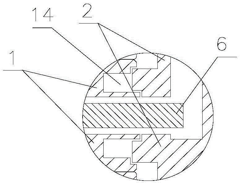
[0031] A three-channel microwave rotary joint, including a single waveguide rotor 1, a double waveguide rotor 3, a double waveguide stator 2, a single waveguide stator 4, a first bearing 501, a second bearing 502, a first connecting arm 9, and a second connecting arm 10 , the first inner conductor 6, the second inner conductor 7 and the third inner conductor 8; the single waveguide rotor 1 and the double waveguide rotor 3 are fixed into rotors by the first connecting arm 9, and the double waveguide stator 2 and the single waveguide stator 4 are fixed by the seco...


PUM


Abstract

The invention discloses a three-channel microwave rotary joint which comprises a single-waveguide rotor, a double-waveguide rotor, a double-waveguide stator, a single-waveguide stator, a first bearing, a second bearing, a first connection arm, a second connection arm, a first inner conductor, a second inner conductor and a third inner conductor. According to the three-channel microwave rotary joint, the axial distance is short, the signal transmission loss is reduced, the problem of multi-channel Ka frequency band signal transmission is solved, the transmit-receive insulation degree is good, double-bearing design is adopted, coaxiality is guaranteed through precise machining and assembling, electrical performance fluctuation generated in the rotating process is greatly lowered, and the reliability of spacecraft moving components is improved.

Description

technical field [0001] The invention relates to a microwave rotary joint, in particular to a three-channel microwave rotary joint, and belongs to the field of aerospace vehicle tracking mechanism design. Background technique [0002] The microwave rotary joint is a special device with the characteristics of electromechanical integration to ensure the uninterrupted transmission of microwave signals during the radar tracking rotation process. [0003] With the development of radar communication technology, the domestic microwave rotary joint technology has been continuously improved, and now it has covered various fields of wireless communication. The technology is very mature, mainly including two types of microwave rotary joints, contact and non-contact. [0004] Existing microwave rotary joints are mainly ground-based communication products, and their structures mainly include single-channel, two-channel and multi-channel forms. In the field of domestic low-earth orbit spac...

Claims


Application Information

Patent Timeline
Patent Type & Authority Applications(China)
IPC IPC(8): H01P1/06H01P3/12
Inventor 杜明亮胡磊陈蓉李连辉郭健李刚刘越东
Owner BEIJING RES INST OF TELEMETRY
Why Eureka
Try Eureka