Garbage plasma gasification furnace taking vapor as gasification medium

A technology of gasification medium and plasma, which is applied in the direction of gasification process, manufacture of combustible gas, petroleum industry, etc., can solve the problems of low gas yield, instability, waste residue treatment and other problems, and achieve uniform flow field and temperature field, The effect of prolonging the service life and reducing operating costs

Active Publication Date: 2015-04-01
中国东方电气集团有限公司
View PDF8 Cites 12 Cited by
  • Summary
  • Abstract
  • Description
  • Claims
  • Application Information

AI Technical Summary

Problems solved by technology

[0004] However, most of the existing garbage plasma gasification furnaces use plasma torches to directly gasify garbage at high temperatures, and generate plasma up to 7000°C through arc discharge, so that the garbage can be completely pyrolyzed, such as Carter’s US Patent US005280757A And Camacho's U.S. Patent US005634414A, the arc plasma is the only heat source, does not use the calorific value of the garbage itself, the energy consumption is high, and the power consumption rate of the plasma torch can reach 30%-45% of its power generation capacity, resulting in the operation The cost is greatly increased, coupled with the limited power of the plasma torch, it is difficult to scale up for commercial application
In addition, because only electric energy is input and the waste is directly gasified by the plasma jet, the temperature field and flow field in the gasification furnace are very uneven, so that the waste cannot be completely treated at high temperature, so that the waste residue contains harmful substances such as dioxins. Bringing greater challenges to waste disposal
[0005] At the same time, the gasification agent used in garbage gasification is usually air, oxygen-enriched or water vapor. When air is used

Method used


Image

  • Garbage plasma gasification furnace taking vapor as gasification medium

Examples


Embodiment Construction

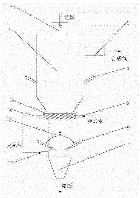
[0024] The present invention provides a garbage plasma gasification furnace using water vapor as the gasification medium, which is composed of an upper garbage gasification chamber 1 and a lower high-temperature steam generation chamber 2, and the upper and lower parts are composed of water-cooled furnace arches arranged at intervals 3 Separated, the inner wall of the gasifier is poured with refractory materials.

[0025] The top of the waste gasification chamber 1 is equipped with a feeding port 4, the side is provided with a syngas outlet 5 at a higher position, and the side is provided with an air supply port 6 at a lower position; the bottom of the high-temperature steam generating chamber 2 is a slag discharge port 7, and the sides are arranged circumferentially Two plasma torches 8, the angle between the two plasma torches 8 is α, and α is 120°-150°; low-temperature water vapor with a temperature of 150°C-250°C is used as the working gas of the plasma torch 8, and at the ...


PUM


Abstract

The invention discloses a garbage plasma gasification furnace taking vapor as a gasification medium. The garbage plasma gasification furnace comprises an upper garbage gasification room and a low high-temperature vapor generating room, wherein water-cooling furnace arches which are arranged at intervals are arranged between the garbage gasification room and the vapor generating room; the garbage gasification room is separated from the high-temperature vapor generating room by virtue of the water-cooling furnace arches; two plasma torches are arranged along the peripheral direction of the inner wall of the high-temperature vapor generating room; low-temperature vapor is taken as a working gas of the plasma torches. According to the garbage plasma gasification furnace disclosed by the invention, the vapor plasmas are adopted to gasify the garbage, so that a high-temperature and high-energy environment is provided for the gasification reaction, and thus, the material heating rate is high and the reaction rate is high, the treatment efficiency is very high and some reactions which cannot be performed under the common gasification condition further can be generated.

Description

technical field [0001] The invention relates to gasification treatment equipment for urban garbage, in particular to a garbage plasma gasification furnace using water vapor as a gasification medium. Background technique [0002] At present, the harmless treatment facilities of municipal solid waste in my country are mainly sanitary landfill, supplemented by composting and incineration. Landfill is recognized as the last choice for waste disposal because it takes up a lot of space and pollutes groundwater. However, the development of composting is still limited due to its high cost, low fertilizer efficiency, poor product marketability, and potential safety hazards. Incineration treatment can achieve comprehensive treatment of waste reduction, harmlessness, and resource utilization to a certain extent, and has obvious advantages in environmental protection and resource utilization, so it has developed rapidly in China. However, direct incineration leads to excessive smoke an...

Claims


Application Information

Patent Timeline
IPC IPC(8): C10J3/20C10J3/80
CPCC10J3/20C10J3/80C10J2300/0946C10J2300/0976C10J2300/1238C10J2300/1687
Inventor 王希李宏张春飞谢斐王晓亮
Owner 中国东方电气集团有限公司
Why Eureka
Try Eureka