Voltage regulation control device for inductive ballast

An inductive ballast and voltage regulation control technology, which is applied in the direction of lighting devices, electric light sources, electrical components, etc., can solve the problems of aggravated power pollution on the power line, increase of high-order harmonics on the power line, and high requirements for circuit control. Effects of wide range, increased power consumption, and high circuit reliability

Inactive Publication Date: 2015-04-01
宋宏伟
View PDF10 Cites 2 Cited by
  • Summary
  • Abstract
  • Description
  • Claims
  • Application Information

AI Technical Summary

Problems solved by technology

Moreover, when the thyristor is chopping and regulating voltage, it will lead to the increase of high-order harmonics on the power line, which will lead to aggravation of power pollution on the power line.
[0005] In some places where the voltage output waveform is relatively strict, an electronic voltage regulator is generally used to adjust the AC input at high frequency, and then perform high-frequency filtering to adjust the output AC value by changing the high-frequency signal. It can reduce the wave interference on the power line, but the field effect tube needs to be used in the circuit for high-frequency conversion, so the high temperature of the field effect tube is caused, and heat dissipation treatment is required. At the same time, the control requirements of the circuit are also very high, and the circuit structure is complicated. At the same time, the external aluminum alloy shell is required for heat dissipation, and the volume is large
If the output voltage adjustment circuit is added inside, the circuit structure will be more complicated

Method used


Image

  • Voltage regulation control device for inductive ballast
  • Voltage regulation control device for inductive ballast
  • Voltage regulation control device for inductive ballast

Examples


Embodiment Construction

[0025] In order to describe the present invention more specifically, the technical solutions of the present invention will be described in detail below in conjunction with the accompanying drawings and specific embodiments.

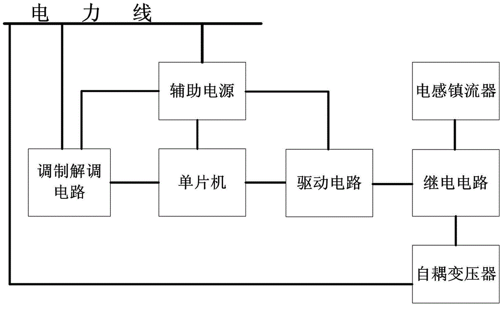
[0026] Such as figure 1 As shown, the voltage regulating control device of the magnetic ballast of the present invention includes: an autotransformer, a single-chip microcomputer, a relay circuit, a drive circuit, an auxiliary power supply, and a modulation and demodulation circuit; wherein:

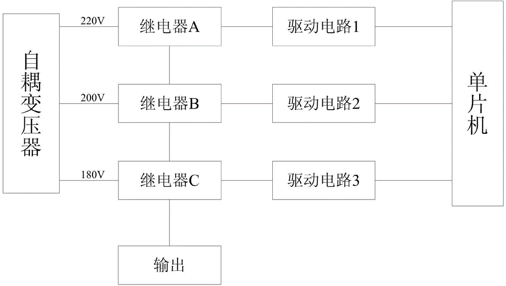
[0027] The autotransformer converts the voltage level of the 220V AC on the power line, and outputs multiple AC working voltages of different voltage levels;

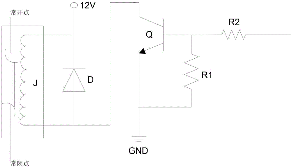
[0028] The driving circuit is connected with the single-chip microcomputer, which receives the driving signal generated by the single-chip microcomputer, and amplifies the power of the signal to control the relay circuit;

[0029] The relay circuit is connected with the drive circuit and the autotransformer,...


PUM


Abstract

The invention discloses a voltage regulation control device for an inductive ballast. The voltage regulation control device comprises a self coupling transformer, a control unit, a relay unit, a driving unit and an auxiliary power supply, wherein the device utilizes the function that a relay can be used as a conversion switch, and the relay is combined with a driving circuit to realize the output and the conversion of a plurality of stages of different voltages, so that power supply voltage required by external equipment is provided. In addition, a user can control the multi-gear voltage output according to concrete requirements, the goal can be achieved only through increasing the corresponding relay and the corresponding driving circuit, simplicity, convenience and high speed are really realized, the requirement of outputting various voltages in a controlled way is met, and the fast and convenient voltage regulation and the maximum efficiency are realized. The voltage regulation control device has the advantages that the defect of a phenomenon that an original inductive ballast cannot realize the single dimming is overcome, no special requirements on power supply of an electric network exist, the linear voltage output can be realized, the power consumption cannot be additionally increased, and in addition, a higher power factor is maintained.

Description

technical field [0001] The invention belongs to the technical field of lighting equipment control, and in particular relates to a voltage regulation control device for an inductance ballast. Background technique [0002] The gas discharge lamps sold in the market today, including sodium lamps, metal halide lamps and other lamps used for conventional outdoor lighting, are traditionally equipped with magnetic ballasts. The magnetic ballasts can be used for a long time during use, and the failure rate is low. , Compared with electronic ballasts, the cost is relatively low, and it has been recognized by many lighting manufacturers and owners. However, the only disadvantage of magnetic ballasts is that they cannot be controlled for energy saving. They can only be guaranteed to work within a fixed voltage range, and cannot achieve the effect of intelligent power saving. [0003] Now there are many energy-saving companies, such as EMC (electromagnetic compatibility) companies, and...

Claims


Application Information

Patent Timeline
Patent Type & Authority Applications(China)
IPC IPC(8): H05B41/36
CPCY02B20/00
Inventor 宋宏伟
Owner 宋宏伟
Why Eureka
Try Eureka