A kind of mold and production equipment for fireworks cylinder body

A technology for forming molds and production equipment, which is applied in the direction of forming indenters, attack equipment, ceramic molding machines, etc., can solve the problems that affect the service life of the mold release mold, the wear of the mold is relatively serious, and the accuracy of the equipment is greatly affected. The product structure is evenly stressed, the production cycle is shortened, and the extrusion molding time is reduced

Inactive Publication Date: 2016-06-29
汤华荣
View PDF13 Cites 0 Cited by
  • Summary
  • Abstract
  • Description
  • Claims
  • Application Information

AI Technical Summary

Problems solved by technology

However, in the process of using this equipment for production, since the vibrating plate is used to drive the core fixing frame to vibrate, thereby realizing the vibration of the raw materials in the core fixing frame, frequent mechanical vibrations have a great impact on the accuracy of the equipment, and the wear of the mold is relatively large. Severe, affecting the demoulding of the mold and the service life of the mold
Due to the mixed moisture in the raw materials, it takes a long time for extrusion and setting before the fireworks cylinder is released from the mold, so as to ensure the firmness before the mold, so as to ensure the successful demoulding of the product, and it takes a long time to dry the product after the mold is released , so the whole production process takes a long time

Method used


Image

  • A kind of mold and production equipment for fireworks cylinder body
  • A kind of mold and production equipment for fireworks cylinder body
  • A kind of mold and production equipment for fireworks cylinder body

Examples


Embodiment Construction

[0036] The present invention will be further described in detail below in conjunction with the accompanying drawings and examples. The following examples are explanations of the present invention and the present invention is not limited to the following examples.

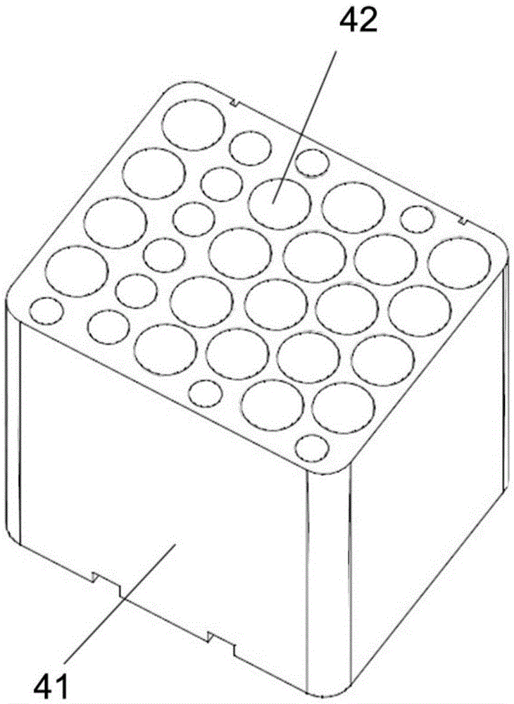
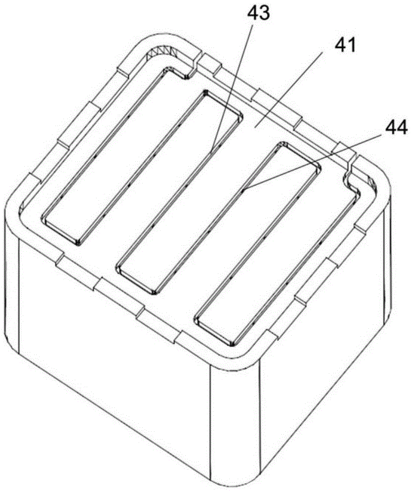
[0037] Such as figure 1 , figure 2 As shown, in this embodiment, the structure of the fireworks cylinder that needs to be molded is as follows: the fireworks cylinder includes a one-time extruded cylinder 41, an upwardly opened emission hole 42, and a lead groove arranged at the bottom of the cylinder 41. 43 and the lead hole 44 arranged on the lead groove 43 and connected to the emission hole 42 .

[0038] The body preparation method for preparing the above-mentioned fireworks tube in this embodiment includes the following steps:

[0039] a. Prepare raw materials, which include plant fibers, fillers and setting-hardening materials, wherein the setting-hardening materials use either air-setting cementitious mater...


PUM


Abstract

The invention discloses a firework barrel forming mold and production equipment. The firework barrel forming mold comprises a mold base, an upper mold and a lower mold. A forming cavity which is used for accommodating raw materials is arranged on the lower mold, ultrasonic vibration heads which are used for transmitting ultrasonic waves to the forming cavity are arranged on the lower mold, the upper mold comprises an upper mold plate and an upper mold cylinder, the upper mold cylinder is used for driving the upper mold plate to move up and down, the lower mold comprises a cavity, the forming cavity, a lower mold plate and a lower mold cylinder, the forming cavity is arranged on the cavity, the lower mold plate is arranged in the forming cavity, the lower mold cylinder is used for driving the lower mold plate to vertically move up and down in the forming cavity, and the ultrasonic vibration heads are fixed onto the cavity. The firework barrel forming mold and the production equipment have the advantages that the raw materials in the forming mold can be vibrated at high frequencies, accordingly, the internal chemical reaction speeds of the raw materials can be increased, the compactness of products and the quality of the products can be improved, drying degrees of the products can be upgraded, the strength of the products stripped from the forming mold can be improved, the products are difficult to break and are easy to carry, and the time required by drying or natural drying in later periods can be shortened.

Description

technical field [0001] The invention relates to a mold for forming a fireworks cylinder and production equipment. Background technique [0002] Traditional fireworks outer cylinders are mainly made by hand, and the main raw material is paper. Its production method is: paper cutting, gluing, roller, trimming, drying, bundling, sealing, drilling, inserting lead wires, etc. At present, this traditional production method is still the most important production method of the outer tube of fireworks. The disadvantages of the above methods are that there are many processes, low processing efficiency, long production time, and a large amount of paper and glue are consumed. [0003] In order to overcome the inefficiency of traditional fireworks outer tubes, many new manufacturing methods have been developed by people in the industry: [0004] The application number is: 200710034745.X, and the patent name is: A Chinese patent application for a shell of fireworks, which discloses a p...

Claims


Application Information

Patent Timeline
Patent Type & Authority Patents(China)
IPC IPC(8): F42B4/30B28B1/087B28B3/04B28B7/00B28B13/02B28B13/04
Inventor 汤华荣
Owner 汤华荣
Why Eureka
Try Eureka