Method for measuring diffusion coefficient and equilibrium concentration of CO2 in process of diffusion from water phase to oil phase

A technology of diffusion coefficient and equilibrium concentration, used in measuring devices, specific gravity measurement, electrical digital data processing, etc.

Active Publication Date: 2015-04-08
CHINA UNIV OF PETROLEUM (EAST CHINA)
View PDF6 Cites 9 Cited by
  • Summary
  • Abstract
  • Description
  • Claims
  • Application Information

AI Technical Summary

Problems solved by technology

[0006] The above-mentioned comparatively representative pressure drop method and the measurement CO disclosed in Chinese patent document CN102706779A 2 The methods of diffusion coefficient in rocks are all for the molecular diffusion coefficient between gas-liquid two phases. At present, for CO 2 Mass transfer and diffusion studies between immiscible oil-water phases, especially CO 2 The measurement of the diffusion coefficient in the process of diffusion from the water phase to the oil phase has not been reported at home and abroad.

Method used


Image

  • Method for measuring diffusion coefficient and equilibrium concentration of CO2 in process of diffusion from water phase to oil phase
  • Method for measuring diffusion coefficient and equilibrium concentration of CO2 in process of diffusion from water phase to oil phase
  • Method for measuring diffusion coefficient and equilibrium concentration of CO2 in process of diffusion from water phase to oil phase

Examples


Embodiment 1

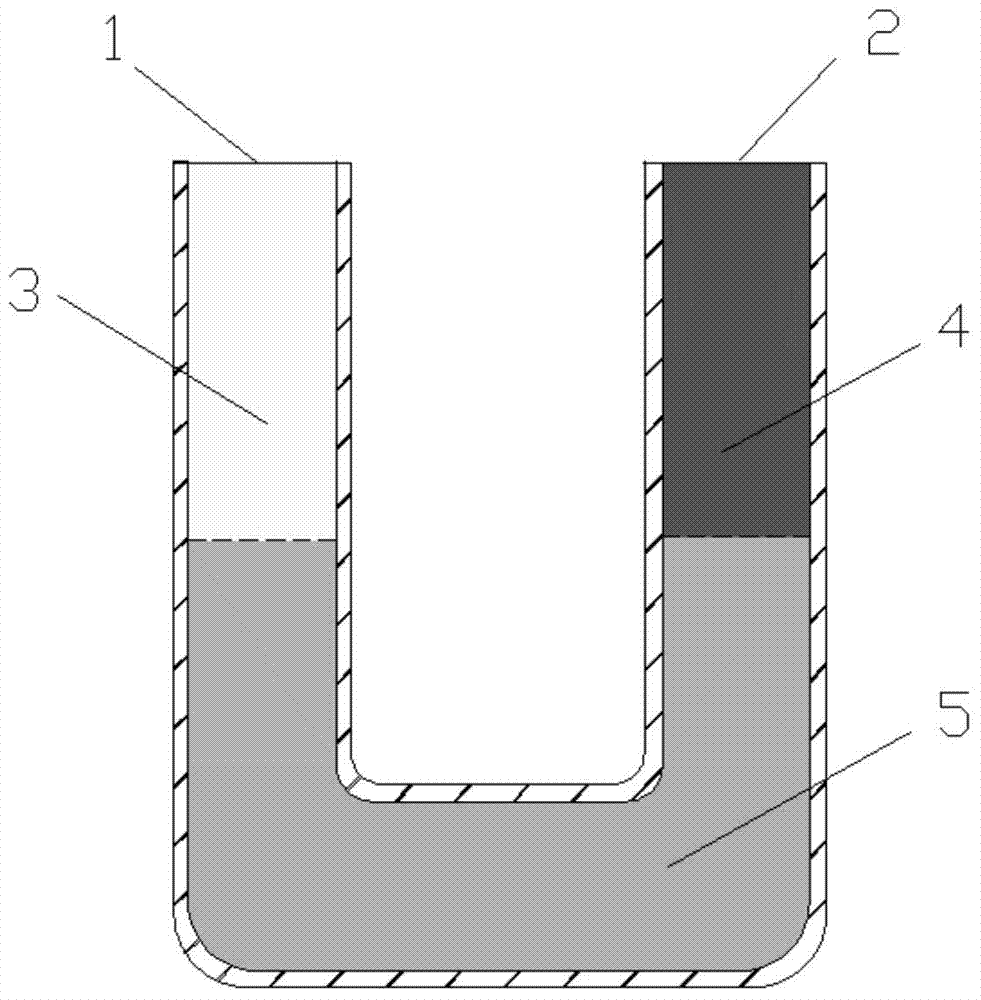
[0064] a CO 2 Method for measuring diffusion coefficient and equilibrium concentration during diffusion from water phase to oil phase, wherein the implementation of the method is applied to a measuring device, the measuring device includes a vertically fixed U-shaped tube, and the U-shaped tube includes a terminal 1 and b-end 2, both the a-end 1 and the b-end 2 are open upwards; the specific steps include:

[0065] (1) Measure the volume V of the U-shaped tube 1 250mL and the cross-sectional area A of the inner diameter of the U-shaped tube 1 8cm 2 , check the airtightness of the whole measuring device;

[0066] (2) Inject distilled water with a temperature of T into the U-shaped tube, so that the U-shaped tube is filled with distilled water, and the value of T is 50°C;

[0067] (3) Connect the back pressure valve connected to the back pressure pump to the b-end 2 of the U-shaped pipe to communicate with the back pressure, and the back pressure pump is set to a predetermin...

Embodiment 2

[0093] According to the measurement method described in Embodiment 1, the difference is that the measurement device also includes COs that are respectively movably connected with the U-shaped tubes. 2 Gas tanks, distilled water tanks and crude oil tanks, the CO 2 The gas tank, the distilled water tank and the crude oil tank are respectively connected with advection pumps.

[0094] CO 2 CO in the tank 2 , the distilled water in the distilled water tank and the crude oil in the crude oil tank are respectively pumped into the U-shaped pipe.

Embodiment 3

[0096] According to the measurement method described in embodiment 1 or 2, the difference is that CO is injected into the U-shaped tube 2 , distilled water and crude oil, the CO 2 The gas tank, the distilled water tank, the crude oil tank and the U-shaped pipe are vacuumed.


PUM


Abstract

The invention relates to a method for measuring the diffusion coefficient and the equilibrium concentration of CO2 in the process of diffusion from a water phase to an oil phase. According to the method, the water-phase saturated CO2 at the bottom of a U-shaped pipe is formed into saturated carbonated water; CO2 is injected into the end a of the U-shaped pipe, and crude oil is injected into the end b of the U-shaped pipe; as CO2 in the water phase diffuses to the oil phase, CO2 in the saturated carbonated water is not saturated again, and therefore, the gaseous-phase CO2 is dissolved in the carbonated water. Pressure change due to the diffusion of the CO2 to the carbonated water is measured, and then the diffusion coefficient of the CO2 during diffusion from the water phase to the oil phase and the equilibrium concentration of the CO2 in the crude oil after equilibrium can be obtained in combination with a pressure drop formula. According to the method, the method for measuring the diffusion coefficient of the CO2 in the process of diffusion from the water phase to the oil phase by use of an improved PVT pressure drop method is provided for the first time, and the method is simple to operate and clear in principle; the diffusion coefficient can be obtained without directly measuring the concentration change of CO2 in the process of diffusion from the water phase to the oil phase; the method is significant for studying the migration and distribution of CO2 between the water phase and the oil phase and guiding oil-gas field development.

Description

technical field [0001] The invention relates to a method for measuring CO 2 The method for diffusion coefficient and equilibrium concentration in the process of diffusion from water phase to oil phase belongs to the technical field of petrochemical industry. Background technique [0002] In recent years, the requirements for reducing greenhouse gas emissions have been increasing all over the world. CO 2 The treatment of exhaust gas has gradually become a problem that needs to be faced and solved urgently in today's society. Treating CO on the oil field 2 The most effective way is to inject it into oil and gas fields, which not only sequesters CO 2 , but also effectively improve the recovery of oil and gas fields. Due to CO 2 It has unique phase characteristics and oil recovery mechanism, making it more and more widely used in the production of low-permeability reservoirs and heavy oil reservoirs. [0003] in CO 2 flooding, CO 2 Throughput and CO 2 In the process of ...

Claims


Application Information

Patent Timeline
Patent Type & Authority Applications(China)
IPC IPC(8): G01N13/00G01N9/36G06F19/00
Inventor 李宾飞叶金桥冀延民李兆敏李松岩董全伟
Owner CHINA UNIV OF PETROLEUM (EAST CHINA)
Why Eureka
Try Eureka