Optical measuring system used for measuring field intensity of direct-current electric field

An optical measurement system and field strength measurement technology, applied in electrostatic field measurement and other directions, can solve problems such as difficult to apply to industrial sites, limited application scope, sophisticated and complex equipment, etc., to improve accuracy and reliability, not easy to electromagnetic interference, increase The effect of flexibility

Active Publication Date: 2015-04-08
TSINGHUA UNIV
View PDF10 Cites 2 Cited by
  • Summary
  • Abstract
  • Description
  • Claims
  • Application Information

AI Technical Summary

Problems solved by technology

However, the above-mentioned electrical measurement method has two disadvantages: first, the field strength meters used are all active devices, which contain electronic circuits, and are prone to failure due to electromagnetic interference in strong electric fields and harsh measurement environments; second , the field strength meter contains metal parts inside, which will cause distortion of the original field at the field point during measurement, which will greatly affect the accuracy of measurement
However, due to the need for AC motors, mechanical transmissions, etc., the scope of application is limited to laboratory environments
And because the equipment is sophisticated and complex, it is difficult to apply to industrial sites

Method used


Image

  • Optical measuring system used for measuring field intensity of direct-current electric field
  • Optical measuring system used for measuring field intensity of direct-current electric field
  • Optical measuring system used for measuring field intensity of direct-current electric field

Examples


Embodiment Construction

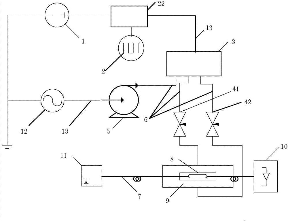
[0014] The optical measurement system for the measurement of the DC electric field intensity proposed by the present invention has a structural schematic diagram as figure 1 As shown, it includes a DC power supply 1, a signal generator 2, a signal drive circuit 22, an electromagnetic reversing valve 3, a first throttle valve 41, a second throttle valve 42, an AC power supply 12, an electric air pump 5, a laser source 11, Rotary device 9 , electric field sensor 8 and detector 10 . The DC power supply 1 and the signal generator 2 are respectively connected to a signal driving circuit 22 . The AC power supply 12 is connected to the input end of the electric air pump 5 through a signal line, and the output end of the electric air pump 5 is connected to the air intake end of the electromagnetic reversing valve 3 through the gas pipeline 6, and the two gas outlets of the electromagnetic reversing valve 3 are respectively connected to the The intake port of the first throttle valve ...


PUM


Abstract

The invention relates to an optical measuring system used for measuring field intensity of a direct-current electric field and belongs to the technical field of direct-current electric field measuring. In the optical measuring system, an output end of a laser source is connected with an input end of an integrated electric field sensor based on common path interference through an input polarization maintaining optical fiber, and optical signals modulated through the electric field are photoelectrically converted by an optical fiber transmission-in detector; an air source after entering an electromagnetic reversing valve gates airflow of two air ways and is input into a rotating device to drive a drum to rotate bidirectionally; a driving circuit drives an electromagnetic valve to realize current conversion. The rotating device at the front end is made by a nonmetal material, so that distortion to a to-be-measured field is reduced; all devices in the optical measuring system are connected flexibly, so that flexibility in measuring mode is improved; a control circuit, the driving circuit and the optical measuring system are isolated fully, so that the optical measuring system is less prone to electromagnetic interference, and accuracy and reliability of measuring results are improved. By the optical measuring system, direct-current electric field distribution on the surface of an object can be measured nearly, so that range of electric fields which can be measured is expanded.

Description

technical field [0001] The invention relates to an optical measurement system for measuring the field strength of a direct current electric field, and belongs to the technical field of direct current electric field measurement. Background technique [0002] DC electric field measurement is widely used in engineering applications and scientific research fields, and it is of great significance to the diagnosis of electrical equipment and the improvement of power transmission efficiency. At present, the research on the measurement method of DC electric field has been widely carried out at home and abroad. According to the measurement principle, it can be divided into two categories: optical method and electrical method. [0003] The electrical measurement method is mainly based on the principle of electromagnetic induction. Usually, the method of rotating or vibrating the induction blade is used to convert the DC electric field into an alternating electric field, forming a rota...

Claims


Application Information

Patent Timeline
Patent Type & Authority Applications(China)
IPC IPC(8): G01R29/12
Inventor 曾嵘崔晓帆俞俊杰汪海
Owner TSINGHUA UNIV
Why Eureka
Try Eureka