Postirradiation fuel rod vacuum bubble method leak detection box and leak detection system and leak detection method thereof

A technology of vacuum bubbles and fuel rods, applied in the direction of reducing greenhouse gases, climate sustainability, nuclear reactor monitoring, etc., can solve the problems of high sealing requirements, low detection sensitivity, difficult installation, etc., to achieve easy installation and structural strength. Guarantee and achieve the effect of sealing

Active Publication Date: 2015-04-08
NUCLEAR POWER INSTITUTE OF CHINA
View PDF9 Cites 10 Cited by
  • Summary
  • Abstract
  • Description
  • Claims
  • Application Information

AI Technical Summary

Problems solved by technology

The water boiling method changes the pressure difference between the inside and outside of the fuel rod by heating water. Due to the limitation of the boiling point of water, the pressure difference generally produced is about 0.2 atm, and the detection sensitivity is relatively low, so it is rarely used.
The supercharging method uses the supercharging device to press the reference gas into the fuel rod through the damaged port or a special hole to change the pressure difference between the inside and outside of the fuel rod. However, this method requires high sealing performance, is difficult to install, and is difficult to be widely used.

Method used


Image

  • Postirradiation fuel rod vacuum bubble method leak detection box and leak detection system and leak detection method thereof
  • Postirradiation fuel rod vacuum bubble method leak detection box and leak detection system and leak detection method thereof
  • Postirradiation fuel rod vacuum bubble method leak detection box and leak detection system and leak detection method thereof

Examples


Embodiment 1

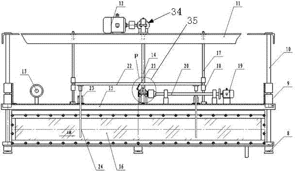
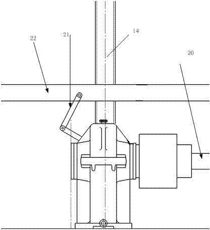
[0062] Such as Figure 1 to Figure 4 shown.

[0063] After irradiation, the fuel rod vacuum bubble method leak detection box includes a leak detection box body 16 with an upper end opening, and a groove is arranged on the upper opening end surface of the leak detection box body, and a sealing strip 4 is arranged in the groove. A cover plate 15 is also arranged above the box body, and the cover plate 15 is provided with a protruding block facing the leak detection box body, and the protruding block is inserted into the groove to seal the upper open end of the leak detection box body.

[0064] Since the present invention adopts the leak detection process on the irradiated fuel rods, the cooperating installation of the above-mentioned groove and the protruding block of the cover plate 15 is realized by the cover plate guide rod 10 and the supporting linear bearing slider 9 automatic positioning At the same time, a protruding block is set under the cover plate to ensure the posi...

Embodiment 2

[0077] Based on the leak detection method of the fuel rod vacuum bubble method leak detection system after irradiation, the leak detection method includes the following steps:

[0078] A. Fuel rod baking step: Use a baking device to bake the surface of the fuel rod; That may exist If the fuel rod is damaged, the fuel rod will be under the water surface for a long time, and the inside will enter the liquid due to the pressure. The vacuum bubble method leak detection adopted in the present invention needs to form a hollow inside the damaged fuel rod with a certain amount of gas, and the bubbles at the damaged part can only be observed when the vacuum bubble method is used for leak detection. Therefore, the present invention uses a roasting device to roast the fuel rods, and discharges the liquid that may exist inside the fuel rods, while other methods for discharging liquids cannot Due to the narrow environment and limited release conditions , not very suitable for the target...


PUM


Abstract

The invention discloses a postirradiation fuel rod vacuum bubble method leak detection box and a leak detection system and a leak detection method thereof. A postirradiation fuel rod is dried through a baking device and then placed in an L-shaped lifting frame and then descends into water inside the leak detection box, the leak detection box is internally vacuumized, the fuel rod generates internal and external differential pressure; if the fuel rod is damaged, bubbles are formed around a damaged opening, the generation positions of the bubbles are determined through image collection, and accordingly the leak detection of the postirradiation fuel rod is finished. The postirradiation fuel rod vacuum bubble method leak detection box has the advantages of quick leak detection speed, simplicity in hot chamber operation and good economy, is simple in structure and low in cost, can be operated through a remote mechanical hand and is safe in structure; no excessive structure is in contact with the fuel rod, the damaged opening appears as far as possible, and the leak detection rate of the fuel rod is improved.

Description

technical field [0001] The patent of the present invention relates to a fuel rod leak detection treatment structure and treatment method. Background technique [0002] At present, the leak detection of fuel rods after irradiation mainly adopts three methods: vacuum bubble method, water boiling method and pressurized method. The water boiling method changes the internal and external pressure difference of the fuel rod by heating water. Due to the limitation of the boiling point of water, the generally generated pressure difference is about 0.2 atm, and the detection sensitivity is relatively low, so it is rarely used. The pressurization method presses the reference gas into the fuel rod through the damaged port or special hole through the pressurization device to change the pressure difference between the inside and outside of the fuel rod. However, this method requires high sealing performance, is difficult to install, and is difficult to be widely used. For a large number ...

Claims


Application Information

Patent Timeline
Patent Type & Authority Applications(China)
IPC IPC(8): G21C17/07
CPCG21C17/07Y02E30/30
Inventor 杨晓冰江林志张显鹏江艳蒋国富宋小蓉李福荣陈军黄伟杰
Owner NUCLEAR POWER INSTITUTE OF CHINA
Why Eureka
Try Eureka