Non-magnetic heating device for nuclear magnetic resonance gyroscope

A nuclear magnetic resonance gyro and magnetic heating technology, which is applied in the direction of electric heating devices, ohmic resistance heating, steering induction equipment, etc., can solve the problems of inability to use miniature nuclear magnetic resonance gyroscopes, excessive transverse magnetic field gradients in gas chambers, and reduced transverse relaxation time, etc. problems, to achieve uniform heating, good thermal insulation performance, and reduce power consumption

Active Publication Date: 2015-04-08
BEIJING INST OF AEROSPACE CONTROL DEVICES
View PDF2 Cites 26 Cited by
  • Summary
  • Abstract
  • Description
  • Claims
  • Application Information

AI Technical Summary

Problems solved by technology

[0003] Hot air heating is a better non-magnetic heating method, but it has insurmountable shortcomings such as large volume and high power consumption, and cannot be used for miniature nuclear magnetic resonance gyro
A. Shkel's research group at the University of California, Irvine used the bottom of the copper rod to heat the atomic gas chamber, and the heating temperature reached 130°C. However, the non-uniform magnetic field introduced by the straight wire reduced the transverse relaxation time of the macroscopic magnetic moment of the inert gas, and the thermal uniformity was poor. lead to poor gyro performance
Northrop Grumman and others used a bidirectional current method to heat the glass gas chamber at the bottom, and obtained high-density alkali metal atom vapor, but there is still the problem that the transverse magnetic field gradient of the gas chamber is too large

Method used


Image

  • Non-magnetic heating device for nuclear magnetic resonance gyroscope
  • Non-magnetic heating device for nuclear magnetic resonance gyroscope
  • Non-magnetic heating device for nuclear magnetic resonance gyroscope

Examples


Embodiment

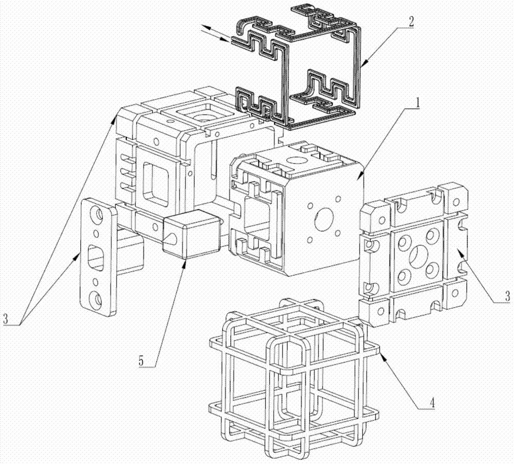
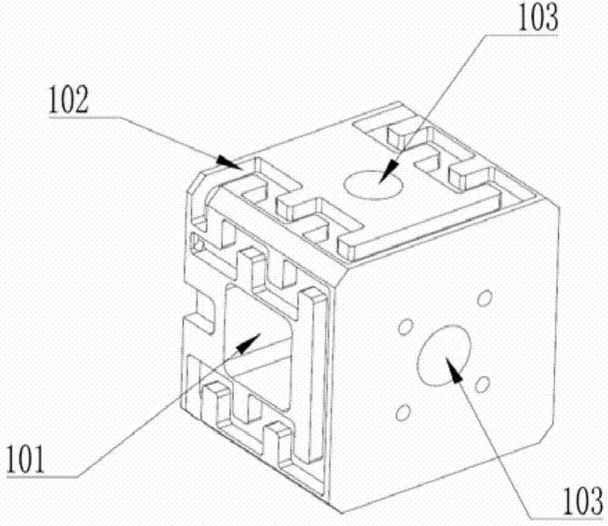
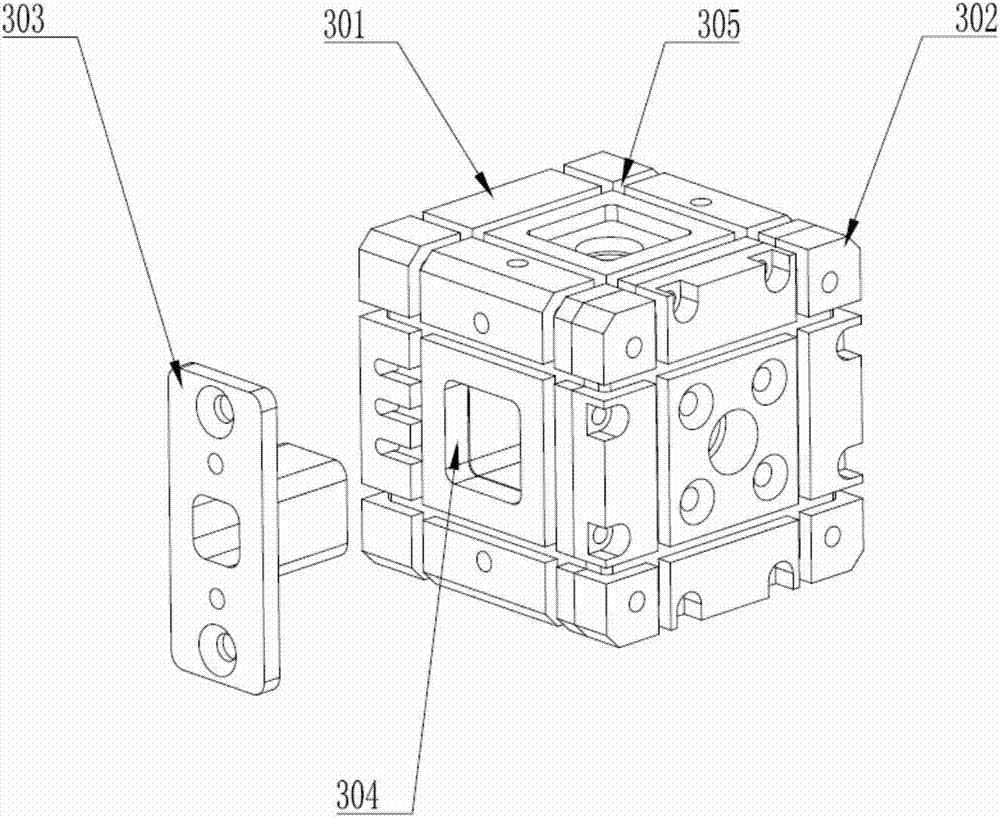
[0044] A non-magnetic heating device for nuclear magnetic resonance gyroscopes, wherein the heating body is made of T2 red copper with a thermal conductivity of 401W / (m.℃). The structure of the heating body is hollow, with a square hole on one side, which can be Put the atomic gas chamber into the inside of the heating body through the square hole. Heating grooves are arranged on four surfaces outside the heating body. The heating wire is made of nickel-chromium alloy heating wire with a total resistance of 3Ω. It is placed in the heating tank in the forward and reverse directions, and is routed under the constraints of the heating tank, forming a spatially symmetrical non-magnetic heating structure. In actual work, the heating current is 2A, and the total heating power is 12W. At the beginning of heating, the heating body is like a stove, which can heat 5 surfaces of the atomic gas chamber at the same time, with high heating efficiency, and the measured temperature differenc...


PUM

PropertyMeasurementUnit
thicknessaaaaaaaaaa

Abstract

The invention provides a non-magnetic heating device for a nuclear magnetic resonance gyroscope. The device consists of a heating body, a heating wire, a heat insulating framework and magnetic compensation coils, wherein the heating body is made of a non-magnetic high-heat-conductivity material, and is of a hollow structure; an atomic gas chamber is placed into the heating body for being uniformly heated; the four faces of the outer side of the heating body are provided with heating grooves; the nickel-chromium alloy non-magnetic heating wire can be placed into the heating grooves positively or reversely, thereby constructing a spatial symmetrical non-magnetic heating structure under the constraints of the heating grooves; after the heating body and the heating wire are fixedly assembled, the combination is fixed in the polytetrafluoroethylene heat insulating framework; three groups of winding grooves are formed in the heat insulating framework for winding enameled wires, thereby constructing three groups of orthogonal Helmholtz magnetic compensation coils for compensating a residual magnetic field. Compared with the prior art, the non-magnetic heating device has the advantages of compact structure, easiness in assembly, easiness in implementing engineering, high heating uniformity, high heating efficiency and high heating magnetic field counteracting capability.

Description

technical field [0001] The invention relates to the technical field of heating of nuclear magnetic resonance gyroscopes, in particular to a non-magnetic heating device for nuclear magnetic resonance gyroscopes. The device is mainly used in the fields of strategic and tactical weaponry, micro space vehicles and the like. Background technique [0002] Miniature nuclear magnetic resonance gyroscopes have the characteristics of small size, low power consumption, high performance, and large dynamic range, and have become the research focus and hotspot of new inertial devices. The performance of NMR gyroscopes is affected by the macroscopic magnetic moment of atomic nucleus spin, which is directly related to the atomic density of alkali metals. In order to improve the signal-to-noise ratio of the gyroscope, it is necessary to heat the atomic gas chamber to above 100°C to obtain high-density alkali metal vapor, and to suppress the negative impact of the heating magnetic field on th...

Claims


Application Information

Patent Timeline
Patent Type & Authority Applications(China)
IPC IPC(8): H01H3/18G01C19/62
CPCG01C19/62H05B3/00
Inventor 王巍王学锋何哲玺刘院省
Owner BEIJING INST OF AEROSPACE CONTROL DEVICES
Why Eureka
Try Eureka