Image acquisition system for breast cancer diagnosis equipment

A technology for image acquisition and diagnosis equipment, which is applied in the field of medical devices and can solve the problems of inability to obtain the intrinsic physiological characteristics of tissues, insufficient precision, and large interference of artifacts.

Inactive Publication Date: 2015-04-22
宁波杜比医疗科技有限公司 +1
View PDF5 Cites 7 Cited by
  • Summary
  • Abstract
  • Description
  • Claims
  • Application Information

AI Technical Summary

Problems solved by technology

[0004] Due to the relatively uniform low-absorption optical properties of breast tissue and the significant optical contrast mechanism provided by the angiogenesis effect of cancerous tissue, such as increased hemoglobin concentration and decreased oxygen saturation, optical breast tomography has the advantages of sensitivity, specificity and safety. Compared with traditional anatomical imaging modalities such as X-ray, magnetic resonance and ultrasound, it has potential comprehensive advantages. Most of the existing optical diagnostic methods only image the optical or fluorescence properties of the tissue: for example, blood oxygen diffusion optical tomography can in principle obtain the intrinsic physiological characteristics used to distinguish the degree of tissue benignity, but due to its serious inverse problem The morbidity of the method and the limitation of relying on the endogenous contrast, this method has the disadvantages of insufficient precision and large artifact interference in practical applications; fluorescence diffusion optical tomography relies on the pharmacokinetic properties of fluorescent agents between diseased and normal tissues The exogenous contrast enhancement (2 to 4 times) mechanism provided by the significant difference between the two can obtain tumor location information more reliably, but cannot obtain the intrinsic physiological characteristics of the tissue

Method used


Image

  • Image acquisition system for breast cancer diagnosis equipment
  • Image acquisition system for breast cancer diagnosis equipment
  • Image acquisition system for breast cancer diagnosis equipment

Examples


Embodiment Construction

[0028] A detailed description will be given below of specific embodiments of the present invention according to the accompanying drawings.

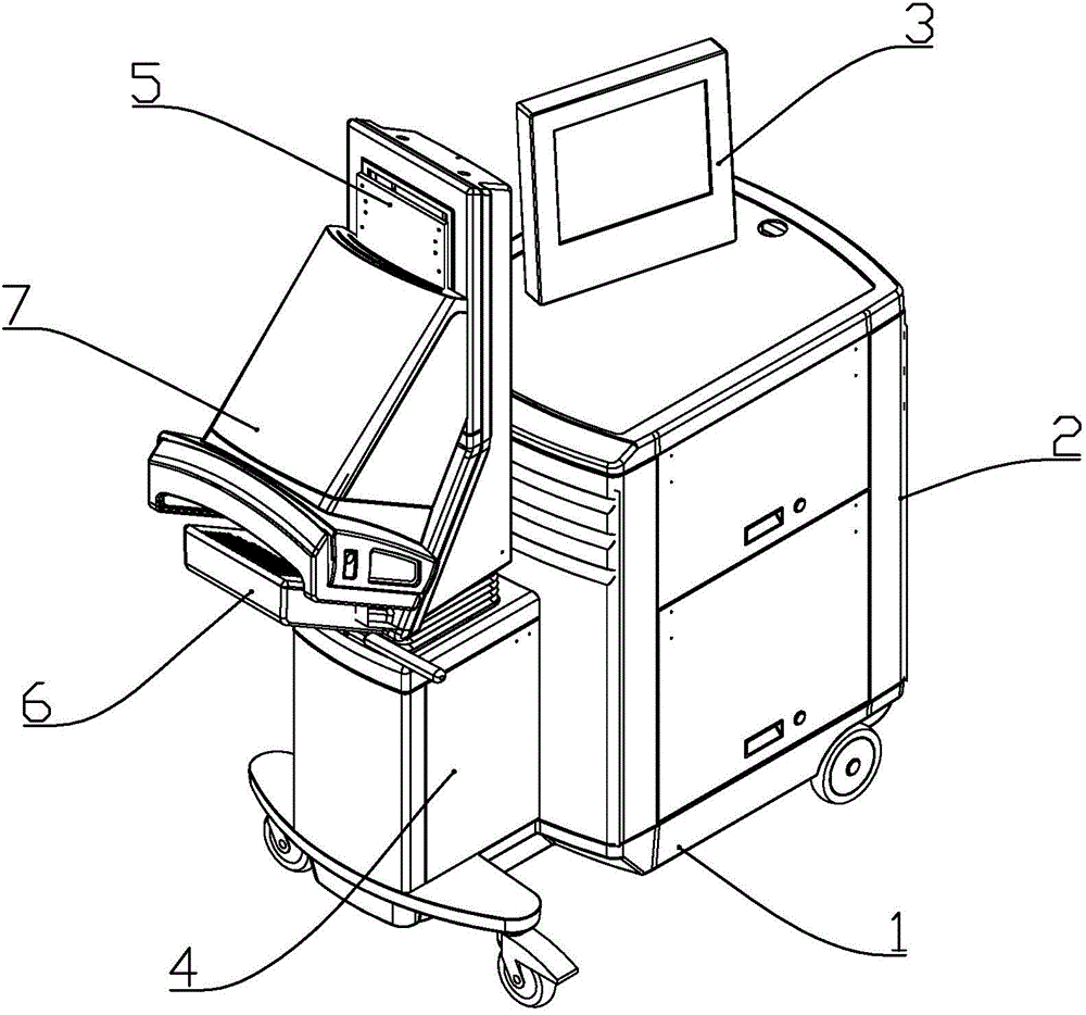
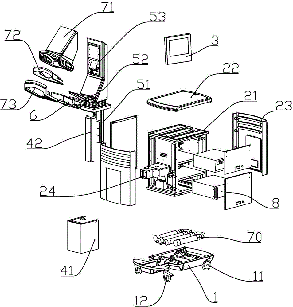
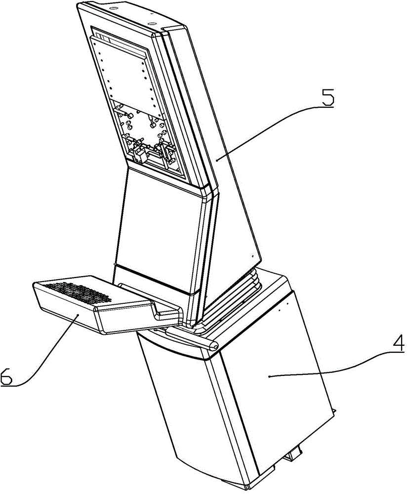
[0029] according to Figure 1 to Figure 4 As shown, the image acquisition system of a breast cancer diagnostic equipment described in this embodiment includes a mounting frame 5, an LED light source 6 for generating infrared light installed on the mounting frame, and an LED light source 6 mounted on the mounting frame. An image acquisition module 7 above the light source is used to receive the infrared light emitted by the LED light source and penetrate the breast to be examined; the wavelength of infrared light produced by the LED light source is between 620nm and 685nm; the image acquisition module includes A CCD camera 74 in order to take dynamic images, and an air bag 72 in order to squeeze breast; Described air bag links to each other with a vacuum tank and an air storage tank 70 by pipeline, and the tube that air bag is connected wi...


PUM

PropertyMeasurementUnit
Wavelengthaaaaaaaaaa

Abstract

The invention discloses an image acquisition system for a breast cancer diagnosis equipment. The image acquisition system for the breast cancer diagnosis equipment comprises a mounting rack, an LED light source which is arranged on the mounting rack and used for producing infrared light, and an image acquisition module which is arranged on the mounting rack and at the upper portion of the LED light source and is used for receiving the infrared light which is emitted by the LED light source and penetrates the examined breast; the image acquisition module comprises a CCD vidicon used for shooting dynamic images and an air bag used for compressing the breast. Uniform distributed pressure can be exerted on the breast by the image acquisition module through the air bag, so that the blood content and the deoxygenated hemoglobin can be driven to produce obvious changes, and therefore mammary gland malignant lesion characteristics detected by adopting the two features of the blood content and the deoxygenated hemoglobin is 6-8 years earlier than that detected by the traditional imaging methods.

Description

technical field [0001] The invention belongs to the field of medical devices, in particular to a special device for diagnosing breast cancer. Background technique [0002] In the scientific community, the process of neovascularization has been shown to be directly linked to the growth and progression of most cancers, as well as to more than 70 other human diseases. [0003] Neovascularization is a key biological process that occurs in healthy and diseased tissues. Under normal conditions, neovascularization is essential for regeneration, embryonic development and wound repair. Under these conditions, a complex process of neovascularization maintains a delicate balance. This balance is accomplished by a variety of neovascularization stimulating growth factors, cardiovascular inhibitors, cell assembly molecules, extracellular matrix and other regulatory factors. However, when this balance is disturbed, too many or too few new blood vessels are produced, leading to vario...

Claims


Application Information

Patent Timeline
IPC IPC(8): A61B5/00
CPCA61B5/004A61B5/0075A61B5/708
Inventor 不公告发明人
Owner 宁波杜比医疗科技有限公司
Why Eureka
Try Eureka