Method for producing methane by virtue of dual-tube passage-type methane generation device with biogas slurry convective stirring function

A generation device and channel-type technology, applied in the field of biogas fermentation system, can solve problems such as uneven distribution, low gas production efficiency, and poor fluidity of biogas slurry, so as to improve the fermentation system and gas production, promote uniform distribution, and strong stirring performance Effect

Inactive Publication Date: 2015-04-22
张伟伟
View PDF0 Cites 0 Cited by
  • Summary
  • Abstract
  • Description
  • Claims
  • Application Information

AI Technical Summary

Problems solved by technology

[0004] The technical problem to be solved by the present invention is that the biogas liquid in the traditional biogas tank has poor fluidity and is easy to crust, and the fermentation raw materials and strains are unevenly distributed in the biogas tank, resulting in low gas production efficiency and low utilization rate of fermentation raw materials

Method used


Image

  • Method for producing methane by virtue of dual-tube passage-type methane generation device with biogas slurry convective stirring function
  • Method for producing methane by virtue of dual-tube passage-type methane generation device with biogas slurry convective stirring function
  • Method for producing methane by virtue of dual-tube passage-type methane generation device with biogas slurry convective stirring function

Examples


Embodiment Construction

[0031] The technical solutions in the embodiments of the present invention will be clearly and completely described below in conjunction with the accompanying drawings in the embodiments of the present invention. Obviously, the described embodiments are only some, not all, embodiments of the present invention. Based on the embodiments of the present invention, all other embodiments obtained by persons of ordinary skill in the art without making creative efforts belong to the protection scope of the present invention.

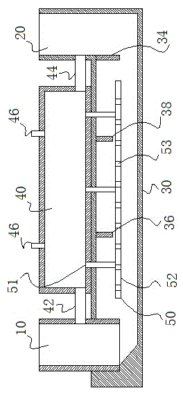
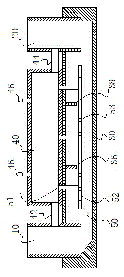
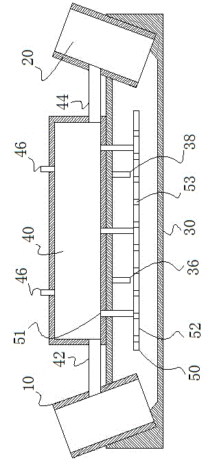
[0032] Such as figure 1 As shown, the methane generation device with double-pipe channel type ultra-high-efficiency biogas slurry convection stirring includes a feed pipe 10, a discharge pipe 20, a fermentation pipe 30 and a hydraulic room 40. The cross-section of the fermentation pipe 30 is circular, rectangular, etc. The geometric shape is obtained by stretching in a straight line. The two ends of the fermentation pipeline 30 are connected to the feed pipe 10 ...


PUM


Abstract

The invention discloses a method for producing methane by virtue of dual-tube passage-type methane generation device with a biogas slurry convective stirring function. According to the method, fermenting raw material is poured inside a fermenting system and fermented to produce methane, methane is respectively gathered inside fermentation zones formed between the side wall of a material inlet / outlet pipe and adjacent air baffle plates or the fermentation zones formed between adjacent air baffle plates so that the methane pressure inside the fermentation zones is increased to push the biogas slurry from a fermenting pipeline to flow towards the material inlet pipe and the material outlet pipe material, the biogas slurry levels in the material inlet pipe and the material outlet pipe continuously rise, and when the lowest point position of the material inlet pipe drainage pipe is firstly reached, the biogas slurry levels in the material inlet pipe and the material outlet pipe further continuously rise, when the lowest point position of the material outlet pipe drainage pipe is reached, the biogas slurry flows inside a hydraulic pressure room from the fermenting pipeline by virtue of the material outlet pipe drainage pipe; when the methane inside any fermentation zone is used, the methane pressure inside the fermentation zone is reduced, the biogas slurry stored in the hydraulic pressure room flows back inside the fermenting pipeline by virtue of the material outlet pipe drainage pipe and the material inlet pipe drainage pipe to complete the circulating flow of the biogas slurry; when the methane inside another fermentation zone is used, methane is circularly produced according to the above steps and used.

Description

technical field [0001] The invention relates to a biogas fermentation system. Background technique [0002] Biogas digesters change the old living habits of farmers and improve the living environment in rural areas. The biogas digesters are built together with toilets and pigpens, which are not easy to breed mosquitoes and have no odor. It will play an important role in eradicating infectious diseases such as schistosomiasis and hookworm. In addition, due to frequent human activities, a large amount of energy consumption, and a large amount of open-air stacking of straw and livestock and poultry manure, etc., have caused a large amount of carbon dioxide emissions and aggravated the greenhouse effect. The use of biogas digesters can reduce the above problems to a certain extent. [0003] Promote the development of ecological agriculture and animal husbandry The waste from the biogas digester is biogas slurry and biogas residue, which can be used as pesticide additives, fert...

Claims


Application Information

Patent Timeline
Patent Type & Authority Applications(China)
IPC IPC(8): C12P5/02C12M1/107C02F11/04
CPCY02E50/30
Inventor 张伟伟
Owner 张伟伟
Why Eureka
Try Eureka