Middle and low-vacuum magnetron sputtering target cathode

A magnetron sputtering, target cathode technology, applied in sputtering coating, vacuum evaporation coating, ion implantation coating and other directions, can solve the problem of high difficulty, high technical requirements for wire cutting and welding, and is not suitable for large-scale promotion, etc. problems, to achieve the effect of improving utilization and life, uniform and adjustable particle size, and simple structure

Active Publication Date: 2015-04-22
CENT IRON & STEEL RES INST
View PDF8 Cites 3 Cited by
  • Summary
  • Abstract
  • Description
  • Claims
  • Application Information

AI Technical Summary

Problems solved by technology

This technology is relatively difficult in the preparation of subsequent target materials, and has high requirements for wire cutting and welding technology, so it is not suitable for large-scale promotion

Method used


Image

  • Middle and low-vacuum magnetron sputtering target cathode
  • Middle and low-vacuum magnetron sputtering target cathode
  • Middle and low-vacuum magnetron sputtering target cathode

Examples


Embodiment 1

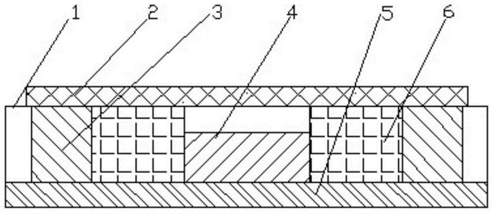
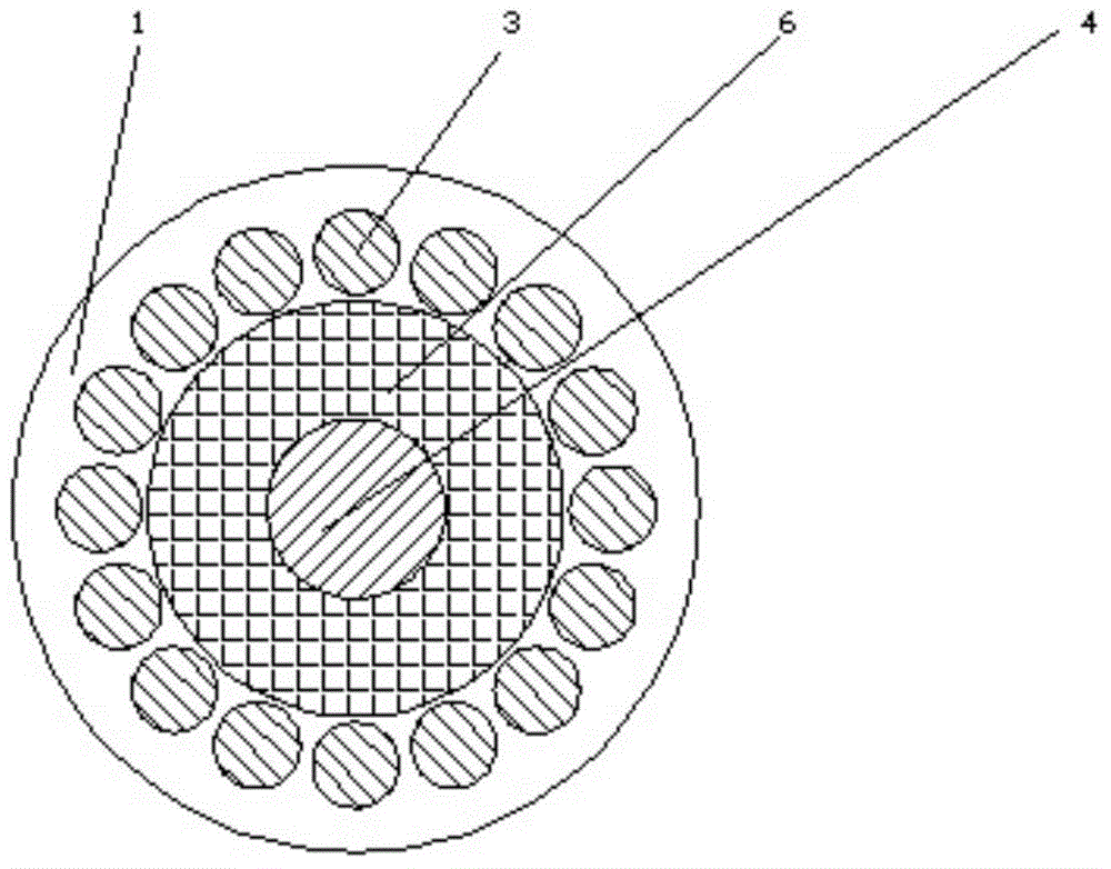
[0043] Embodiment 1 of the present invention uses the magnetron sputtering target cathode for medium and low vacuum designed by the present invention to carry out magnetron sputtering, wherein, the diameter of the outer magnet is 8mm, the height is 15mm, and the number of outer magnets is 20; The diameter of the magnet is 24mm, and the height is 14mm; the thickness of the target 2 is 5mm, and the composition is Al; the sputtering power is 80W, the working pressure is 80Pa, and the sputtering deposition time is 1.5h.

Embodiment 2

[0045] Embodiment 2 of the present invention adopts the magnetron sputtering target cathode for medium and low vacuum designed by the present invention to carry out magnetron sputtering, wherein, the diameter of the outer magnet is 14 mm, the height is 15 mm, and the number of outer magnets is 13; The diameter of the magnet 4 is 24mm, and the height is 5mm; the thickness of the target 2 is 0.5mm, and the composition is Fe 50 co 50 ; The sputtering power is 80W, the working pressure is 80Pa, and the sputtering deposition time is 1.5h.

Embodiment 3

[0047] Embodiment 3 of the present invention is to use the magnetron sputtering target cathode for medium and low vacuum designed by the present invention to carry out magnetron sputtering, wherein, the diameter of the outer magnet is 12 mm, the height is 15 mm, and the number of outer magnets is 16; The diameter of the magnet 4 is 24mm, and the height is 10mm; the thickness of the target 2 is 3mm, and the composition is Fe 50 Ni 50 ; The sputtering power is 80W, the working pressure is 80Pa, and the sputtering deposition time is 1.5h.


PUM

PropertyMeasurementUnit
thicknessaaaaaaaaaa
thicknessaaaaaaaaaa
diameteraaaaaaaaaa

Abstract

The invention belongs to the technical field of production equipment for magneto-controlled sputter coating and particularly relates to a middle and low-vacuum magnetron sputtering target cathode. The magnetron sputtering target cathode comprises a cathode shell (1), a target (2), an outer magnet (3), an inner magnet (4), a base (5) and a cooling channel (6), wherein the cathode shell (1) is in a shape of a hollow cylinder, the outer magnet (3) is embedded in the side wall of the cylinder, the inner magnet (4) is arranged in the center of the cathode shell (1), the cooling channel (6) is arranged between the inner magnet (4) and the cathode shell (1), the target (2) is arranged on the upper surface of the cathode shell (1), the base (5) is arranged on the lower surface of the cathode shell (1), and the height difference between the inner magnet (4) and the outer magnet (3) is 1-10mm. The utilization rate of the target is increased by adopting the method of optimizing the structure of the magnetron sputtering target cathode. The magnetron sputtering target cathode provided by the invention is simple in structure, is strong in operability and is reliable in performance.

Description

technical field [0001] The invention belongs to the technical field of magnetron sputtering coating production equipment, and in particular relates to a magnetron sputtering target cathode used in medium and low vacuum. The utilization rate of the target is improved by optimizing the structure of the magnetron sputtering target cathode. Background technique [0002] Magnetron sputtering is under the action of the static magnetic field generated by the permanent magnet. When the cathode is working, due to the limitation of the glow discharge area, the ionization degree of the area with the largest parallel component of the magnetic field on the target surface is enhanced, and the ionized process gas ions are limited in a narrow space. On the circular "runway", only a part of the target surface is sputtered intensively. After sputtering, a ring-shaped "racetrack"-shaped pit is left on the target surface, and a narrow etching area is formed on the corresponding target surface. ...

Claims


Application Information

Patent Timeline
Patent Type & Authority Applications(China)
IPC IPC(8): C23C14/35
CPCC23C14/3407
Inventor 欧修龙何峻夏振军赵栋梁
Owner CENT IRON & STEEL RES INST
Why Eureka
Try Eureka