
Flue gas ultra-clean wet dust collection system of power plant

A wet dust removal and flue gas technology, which is applied in separation methods, chemical instruments and methods, and dispersed particle separation, etc., can solve the problems of large operating resistance, decreased dust removal efficiency, and unsatisfactory PM2.5 removal effect.

Inactive Publication Date: 2015-04-29
HUANENG CLEAN ENERGY RES INST
View PDF8 Cites 4 Cited by
  • Summary
  • Abstract
  • Description
  • Claims
  • Application Information

AI Technical Summary

Problems solved by technology

[0005] However, electrostatic precipitators also have their own limitations. The removal rate of dust with a particle size of 0.1 μm to 3.0 μm is low, and the removal rate of dust with a diameter of 0.1 μm to 1.0 μm is the lowest, usually lower than 85%. PM2.5 removal effect is not ideal
In addition, the dust removal efficiency of the electrostatic precipitator is affected by many factors (such as electrode structure and shape, flue gas flow rate, fly ash characteristics, etc.), fluctuates greatly, is sensitive to changes in coal types, and the hit rate of the design driving speed is low. If the resistance is too small, it will easily cause secondary dust, and if the specific resistance of dust is too large, it will cause back corona, which will lead to a rapid decline in dust removal efficiency
[0006] In addition, the bag filter also has shortcomings, such as large running resistance, the life of the filter bag filter material is affected by the temperature of the flue dust, acid dew point, etc., and the dust removal of the bag filter currently does not meet the ultra-clean emission standards

Method used


Image

  • Flue gas ultra-clean wet dust collection system of power plant

Examples


Embodiment Construction

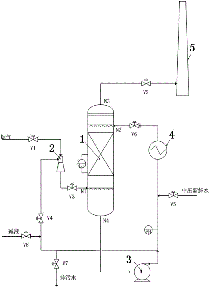
[0015] The structural principle and working principle of the present invention will be described in detail below in conjunction with the accompanying drawings.

[0016] Referring to the accompanying drawings, a power plant flue gas ultra-clean wet dust removal system includes a scrubber 1, the lower interface N1 of the scrubber 1 communicates with the outlet of the Venturi scrubber 2 through the first control valve V3, and the Venturi scrubber 2 The inlet of the boiler is connected to the outlet flue gas at the tail of the boiler through the first control valve V1 and the pipeline.

[0017] The circulating water pipeline at the lower part of the washing tower 1 is provided with a washing tower circulating pump 3, the outlet of the washing tower circulating pump 3 is provided with a circulating water heat exchanger 4, and the pipeline between the washing tower circulating pump 3 and the circulating water heat exchanger 4 is provided with a pH The value measuring device is conne...


PUM


Abstract

The invention discloses a flue gas ultra-clean wet dust collection system of a power plant. A scrubbing tower is communicated with a venturi scrubber connected with flue gas at the outlet of the tail part of a boiler; the bottom of the scrubbing tower is provided with a scrubbing tower circulation pump; the scrubbing tower circulation pump has two outlets, one outlet is connected with the venturi scrubber, and the other outlet is connected with a circulation water heat exchanger; an outlet of the circulation water heat exchanger is connected with a connector at the upper part of the scrubbing tower; an outlet at the top of the scrubbing tower is connected with a chimney; ash in flue gas from the tail part of the boiler is mainly removed by the venturi scrubber and the scrubbing tower; flue gas passes through the venturi scrubber, so that the ash content is soaked fully and then is removed by the scrubbing tower; ash water extracted from the lower middle part of the scrubbing tower is pressurized by a circulation pump of the scrubbing tower to act as scrubbing water of the venturi scrubber; in order to improve the removing efficiency of acid gas, an alkaline solution can be added into ash water which is introduced into the scrubbing tower; boiler feed water serving as fresh supplied water is added into the circulation solution of the tower. The system is simple in structure, is low in investment, and is high in dedusting efficiency.

Description

technical field [0001] The invention relates to a technology for dust removal of flue gas in a power plant, in particular to an ultra-clean wet dust removal system for flue gas in a power plant. Background technique [0002] my country's primary energy structure determines that the pattern of using coal as the main fuel for power generation will not change. More than 80% of the country's electricity comes from thermal power stations, and coal for thermal power generation accounts for more than half of the country's coal output. The environmental pollution caused by coal combustion has seriously restricted the better and faster development of China's energy industry and even the entire national economy. Coal-burning flue gas contains a large number of fine particles (particle size less than 50 μm), of which the proportion of PM10 can reach 40%, while ultrafine particles PM2.5 account for 40% to 70% of PM10. PM2.5 mainly comes from the high-temperature combustion of coal. It...

Claims


Application Information

Patent Timeline
IPC IPC(8): B01D47/14B01D47/10B01D53/78B01D53/40B01D53/96
Inventor 许世森李明亮王保民王剑钊
Owner HUANENG CLEAN ENERGY RES INST
Learn More