Gear shaft part hot-pressing assembly technology automatic production system

An assembly process and production system technology, applied in metal processing, manufacturing tools, metal processing equipment, etc., can solve problems such as difficulty in liquid nitrogen preparation, danger, and stable and uncertain parts quality, so as to reduce labor intensity and danger , high degree of automation, and improved processing efficiency

Active Publication Date: 2015-04-29
SHANGHAI AUTOMOBILE GEAR WORKS
View PDF4 Cites 9 Cited by
  • Summary
  • Abstract
  • Description
  • Claims
  • Application Information

AI Technical Summary

Problems solved by technology

[0006] However, the disadvantages of this technology are: 1) The temperature difference between the pinion shaft and the torsion bar during the bonding period is about 200-300°C. If the heating temperature is too high, it is easy to cause heat treatment tempering of the parts, which will reduce the surface hardness of the parts and affect Performance; 2) Using liquid nitrogen to cool the torsion bar, the preparation of liquid nitrogen is difficult, the price is high, and there are special requirements for transportation and storage, which has certain risks and is not suitable for storage in production sites with many operators; 3) This technology There is no measuring device for the outer diameter or aperture of parts such as pinion shafts and torsion bars. After unqualified parts are mixed in, they cannot be installed correctly, so that the process requirements cannot be met; 4) This technology does not have the function of reading two-dimensional codes. Information such as outer diameter, heating time, and temperature cannot be traced; 5) This technology does not involve a demagnetization unit, and the magnetism generated after induction heating will remain on the parts; 6) This technology cannot accurately control the heating time and heating temperature; 7) It does not constitute a System, due to the high temperature and short time during manual operation, there are certain safety hazards, and it also brings uncertain factors to the stability of parts quality

Method used


Image

  • Gear shaft part hot-pressing assembly technology automatic production system
  • Gear shaft part hot-pressing assembly technology automatic production system
  • Gear shaft part hot-pressing assembly technology automatic production system

Examples


Embodiment 1

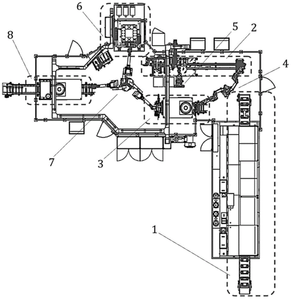
[0042] As shown in Figure 1, the system of this embodiment includes: a cleaning mechanism 1, a gear heating unit 2, a shaft cooling unit 3, a heat pressing unit 6, a cooling and demagnetizing unit 8, and three six-degree-of-freedom manipulators 4, 5, and 7, among which : The gear heating unit 2 and the shaft cooling unit 3 are arranged side by side between the cleaning mechanism 1 and the hot pressing unit 6, the first six-degree-of-freedom manipulator 4 is located between the gear heating unit 2, the shaft cooling unit 3 and the cleaning mechanism 1, and the second The manipulator 5 is located on the side of the gear heating unit 2 , and the third manipulator 7 is located between the heat pressing unit 6 , the shaft cooling unit 3 and the cooling and demagnetizing unit 8 .

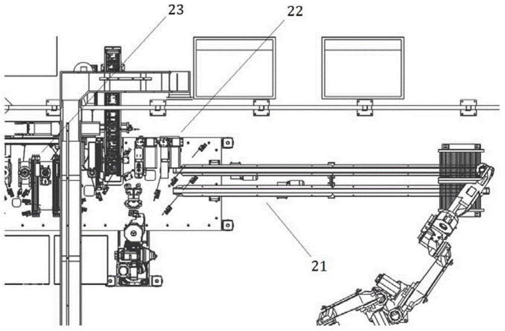
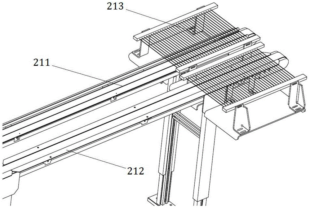
[0043] like Figure 2a , 2b As shown, the gear heating unit 2 includes: a gear feeding device 21, a gear detection unit 22, and a gear heating unit 23 connected in sequence, wherein:

[0044] The gear f...


PUM


Abstract

A gear shaft part hot-pressing assembly technology automatic production system comprises a cleaning mechanism, a gear heating unit, a shaft cooling unit, a hot pressing unit, a cooling demagnetizing unit and three six degree of freedom manipulators; the gear heating unit and the shaft cooling unit are arranged between the cleaning mechanism and the hot pressing unit; the first six degree of freedom manipulator is arranged between the gear heating unit, the shaft cooling unit and the cleaning mechanism; the second six degree of freedom manipulator is arranged on one side of the gear heating unit; heating of two gear parts, cooling the shaft part and interference assembling of the three parts are achieved through the third six degree of freedom manipulator. According to the gear shaft part hot-pressing assembly technology automatic production system, the machining efficiency is greatly improved, the operation is simple, the automatic degree is high, assembling is easy, the performance is stable, and the quality of machined parts is reliable.

Description

technical field [0001] The invention relates to an automation technology in the field of interference fit processing, in particular to an automatic production system of a hot-press assembly process for gear shaft parts. Background technique [0002] Traditionally, the input shaft and the driving gear are press-fitted, usually using spline fit or directly adopting an integrated design. For the one-piece design, there are often defects such as interference in the machining process, increased manufacturing difficulty, waste of forging materials, and difficult heat treatment. The main defect of spline pressing is to increase the risk of spline manufacturing and quality control. Compared with the existing solutions, the hot pressing process is simple to manufacture. It only needs to perform ordinary grinding on the inner hole of the part and the outer diameter of the shaft. There is no special process, and the forging and manufacturing difficulty of each part is reduced, saving ...

Claims


Application Information

Patent Timeline
Patent Type & Authority Applications(China)
IPC IPC(8): B23P11/02
CPCB23P11/025
Inventor 费宁忠杨立马森林黄明礼
Owner SHANGHAI AUTOMOBILE GEAR WORKS
Why Eureka
Try Eureka