
A Method for Producing Reinforced Concrete Pipes by Extruding and Demolding with Dual Vibration Sources

A reinforced concrete pipe, double vibration technology, applied in the direction of mold, reinforced molding, ceramic molding machine, etc., can solve the problems of reducing the service life of equipment, using more manpower, damage and wear, etc. Environmental protection, the effect of using less power

Inactive Publication Date: 2017-01-25
李荣耀 +3
View PDF8 Cites 0 Cited by
  • Summary
  • Abstract
  • Description
  • Claims
  • Application Information

AI Technical Summary

Problems solved by technology

[0005] However, the pipe-making methods of "mandrel vibration", "centrifugal" or "suspension roller" represented by the above-mentioned patent documents still have the following disadvantages:
[0007] 2. The "centrifugal", "suspension roller" and "mandrel vibration method" are used to produce concrete pipes. Because the mold or mandrel needs to rotate, it is difficult to control the process of conveying concrete raw materials during production, and it is difficult to use advanced equipment with high transmission efficiency. , so the use of manpower is large and the production efficiency is low
[0008] 3. Using "centrifugal", "suspension roller" including "mandrel vibration method" to produce reinforced concrete pipes, there are many transmission and rotating equipment, which will be damaged and worn during the production process, the failure rate is high, and the amount of maintenance is large, which directly affects Production efficiency and increased production costs
Insufficient thixotropic reaction of concrete
The plasticization and liquefaction degree of concrete is poor. Therefore, using the existing "mandrel vibration method" to produce the outer mold and inner mold structure of reinforced concrete pipes, the demoulding is inconvenient, and the produced concrete pipe wall is very rough. And it is inconvenient to demould, and it is easy to cause the defect of concrete pipe collapse and deformation
[0010] 5. When using "centrifugal", "suspension roller" including "mandrel vibration method" to produce reinforced concrete pipes, there is no special cover structure to isolate the operator from the pipe making equipment. Therefore, on the one hand, the existing manufacturing The pipe equipment cannot provide a working platform for the operator to operate intuitively. On the other hand, it cannot guarantee that the reinforced concrete raw materials or other impurities will fall into the gaps of the various parts of the pipe making equipment. In severe cases, the pipe making equipment will stop working and affect the work efficiency and reduce the service life of the equipment

Method used


Image

  • A Method for Producing Reinforced Concrete Pipes by Extruding and Demolding with Dual Vibration Sources
  • A Method for Producing Reinforced Concrete Pipes by Extruding and Demolding with Dual Vibration Sources
  • A Method for Producing Reinforced Concrete Pipes by Extruding and Demolding with Dual Vibration Sources

Examples


Embodiment 1

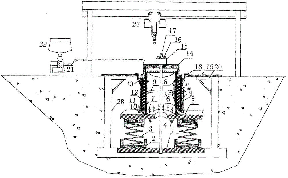
[0082] The invention provides a vibrating table structure for producing a reinforced concrete pipe system by extruding and demoulding with dual vibration sources, the vibrating table includes a vibrating table base plate 1, a spring limit seat 2, a supporting spring 3, a vibrating table high-frequency The vibrator 4 and the vibrating table bottom plate 5, the upper end of the supporting spring 3 is fixed to the vibrating table bottom plate 5 through the spring limiting seat 2, the lower end of the supporting spring 3 is fixed to the vibrating table base plate 1 through the spring limiting seat 2, and the high frequency of the vibrating table The vibrator 4 is fixed below the vibrating table bottom plate 5; the vibrating table base plate 1 is fixed at the bottom of the foundation pit 28; the supporting spring 3 is a conical spring with a small upper part and a larger lower part; A support spring 3 constitutes an elastic support structure, the elastic support structure is at leas...

Embodiment 2

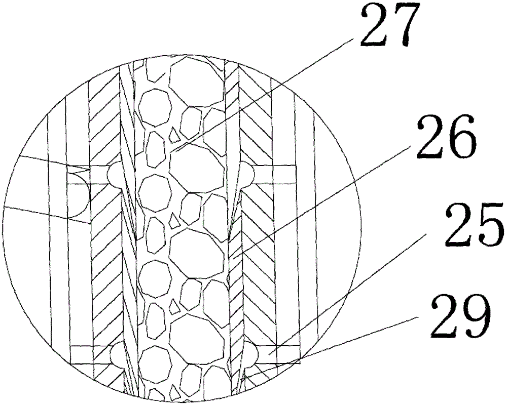
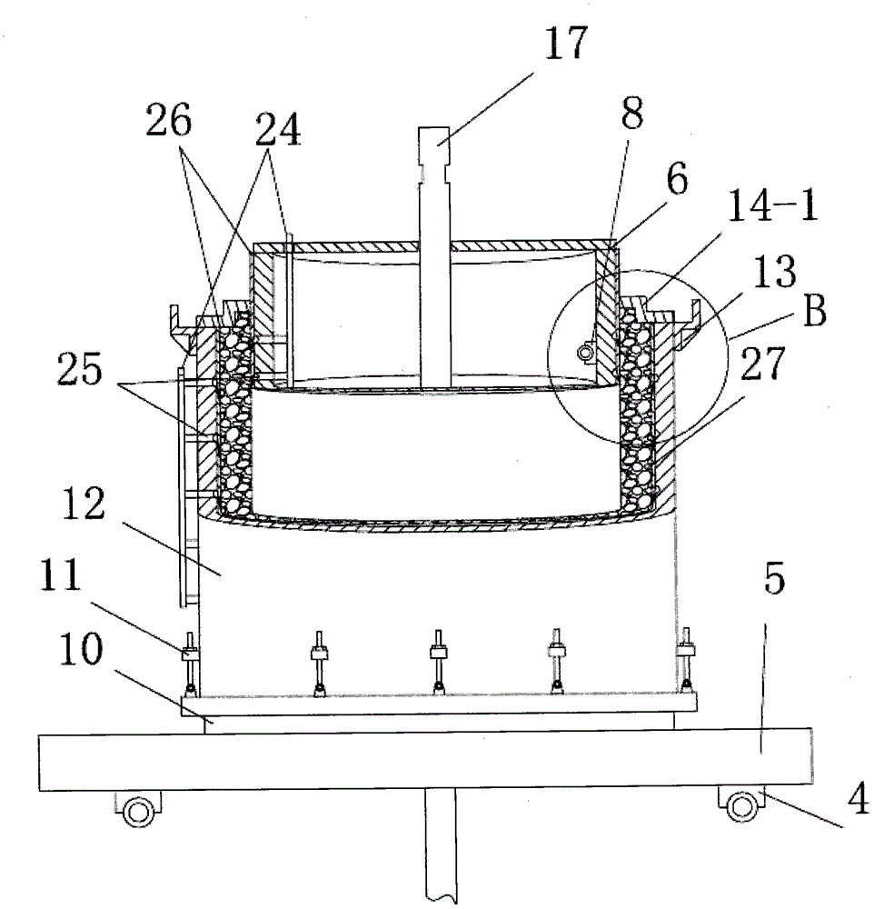
[0084] The invention provides an inner circular mold vibrating cylinder for producing a reinforced concrete pipe system by extruding and demolding with double vibration sources, the inner circular mold vibrating cylinder comprises an inner circular mold cylinder 6, an inner circular mold connecting bolt 7, an inner circular mold The support ring 9 and the high-frequency vibrator 8 of the inner circle mold, the inner circle mold barrel 6 is installed on the vibrating table of the pipe system through the inner circle mold connecting bolt 7, and the inner circle mold support ring 9 is installed on the inner circle mold barrel 6 Among them, the inner circular mold high frequency vibrator 8 is installed on the inner wall of the inner circular mold cylinder 6; There are a plurality of stripping rings, which are plugged to form a stripping outer wall that matches the shape of the outer wall of the inner mold cylinder 6, and the upper end of the next stripping ring presses the lower en...

Embodiment 3

[0086] The invention provides an outer circular mold barrel structure for producing reinforced concrete pipe system through extrusion and demoulding with double vibration sources. 12 and mold retaining ring 13, the inner circle mold barrel 6 is located in the outer circle mold barrel 12 and the annular cavity for producing reinforced concrete pipe 27 is formed between the inner and outer circle mold barrels 12, and the outer circle mold bottom ring 10 passes through the outer circle mold The connecting bolt 11 is used to be installed on the bottom end of the outer cylindrical mold barrel 12 and close the bottom of the annular cavity, and the mold stop ring 13 is sleeved on the outer wall of the outer cylindrical mold barrel 12 and protrudes from the outer cylindrical mold barrel 12 The top of the outer circular mold cylinder 12 is shaped as a truncated cone with a small upper part and a larger lower one; a plurality of demoulding rings are set on the inner wall of the outer cyl...


PUM

PropertyMeasurementUnit
diameteraaaaaaaaaa
heightaaaaaaaaaa

Abstract

The invention discloses a method for producing a reinforced concrete pipe by extrusion demolding of double vibration sources. The method comprises the following steps of A, digging a foundation pit in the ground surface, and arranging a material conveying device and a hoisting device outside the foundation pit; B, installing vibration platforms, an inner circular die vibration tube and an outer circular die tube structure in the foundation pit; C, arranging a baffle plate supporting structure covering the foundation pit above the foundation pit; D, leading concrete raw materials inputted by the material conveying device into an annular cavity between the inner circular die vibration tube and the outer circular die tube, and starting high-frequency vibrators; F, starting a hydraulic extrusion device to carry out physical extrusion after the annular cavity is fully filled with concrete; G, separating the reinforced concrete pipe from the inner circular die vibration tube after the extrusion forming; H, finally separating the outer circular die tube structure from the reinforced concrete pipe. The reinforced concrete pipe produced by utilizing the method has a smooth inner pipe wall and a smooth outer pipe wall; the method disclosed by the invention has the advantages that the safety is good, the operation is convenient, the production efficiency is high, the maintenance is convenient, the pipe manufacturing process is environment-friendly, and an obvious advantage is obtained for producing a series of large-diameter reinforced concrete pipes.

Description

technical field [0001] The invention relates to the technical field of concrete pipe manufacturing methods, in particular to a method for producing reinforced concrete pipes through double vibration source extrusion and demoulding. Background technique [0002] Concrete means concrete, and reinforced concrete pipes are commonly known as reinforced concrete pipes. Reinforced concrete pipes have many advantages such as anti-corrosion and anti-seepage, high compressive strength, long service life, easy manufacture, and low production cost. At present, they are used as the main pipe network buildings for urban waterlogging and urban and rural capital construction drainage. [0003] With the gradual increase of the state's efforts in urban and rural infrastructure construction, and increasing emphasis on improving the urban and rural environment and improving people's living standards as a whole, more and more engineering construction has been put on the table. And engineering c...

Claims


Application Information

Patent Timeline
Patent Type & Authority Patents(China)
IPC IPC(8): B28B21/28B28B21/58B28B21/82B28B21/90
CPCB28B21/28B28B21/60B28B21/82B28B21/90
Inventor 李荣耀仲德金仲敏李荣全
Owner 李荣耀
Learn More