Method for directly liquefying coal

A technology of direct coal liquefaction and coal slurry, which is applied in the preparation of liquid hydrocarbon mixtures, the petroleum industry, and the treatment of hydrocarbon oils. It can solve the problems of reducing the gas content of the reactor, affecting the utilization efficiency of the high-pressure reaction system, and high gas content. Achieve the effect of easy and stable operation control, uniform load, and reduced construction investment

Active Publication Date: 2015-04-29
BLOOMING BEIJING TECH
View PDF5 Cites 6 Cited by
  • Summary
  • Abstract
  • Description
  • Claims
  • Application Information

AI Technical Summary

Problems solved by technology

The reactors selected by these technologies all show a common feature, that is, the gas content in the reactor is too high, which affects the utilization efficiency of the high-pressure reaction system. For example, the German IGOR technology and the Japanese NEDOL technology adopt slurry bed reaction The gas

Method used


Image

  • Method for directly liquefying coal
  • Method for directly liquefying coal
  • Method for directly liquefying coal

Examples


Example Embodiment

[0035] 1. The first preferred embodiment of the present invention

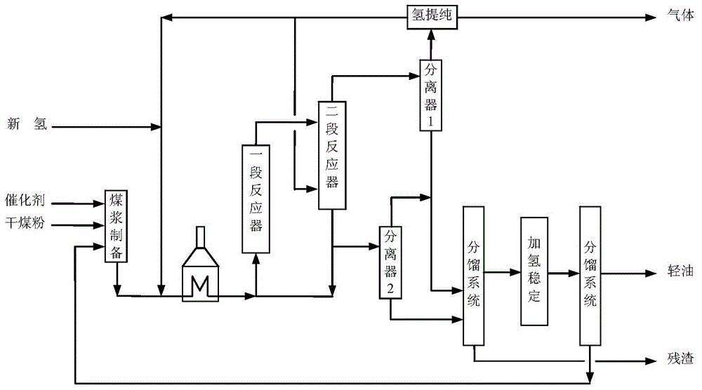
[0036] The principle technological process of this embodiment is as follows figure 1shown. Dry coal powder, catalyst and solvent oil are formulated into coal slurry according to a certain ratio. After the raw material pump (not shown in the figure) boosts the pressure, it is mixed with hydrogen and enters the heating furnace. In the heating furnace, the coal slurry, hydrogen and catalyst The mixture is heated to a temperature close to the inlet of the first-stage reactor (wherein the reaction zone is the first reaction zone), and then enters the bottom of the first-stage reactor, and the mixture composed of coal slurry, hydrogen, and catalyst flows into the first-stage reactor It flows upward and reacts under the condition of direct liquefaction of slurry bed coal. The reaction product flows out from the top of the first-stage reactor and all enters the upper part of the second-stage reactor (the reaction are...

Example Embodiment

[0055] Example 1

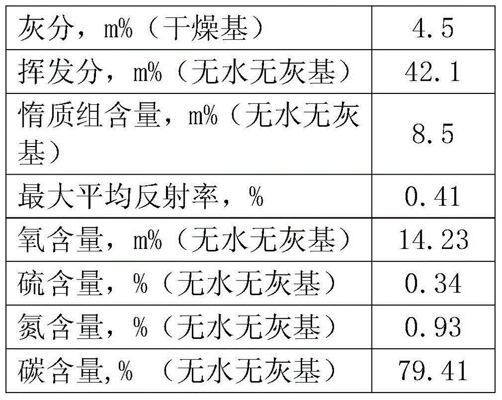
[0056] use figure 1 In the process shown, the pulverized coal is made from a certain long-flame coal, and the properties of the long-flame coal are listed in Table 1. The catalyst is a solid powder catalyst with a maximum particle size of 5 μm and an average particle size of 0.8 μm. The catalyst contains 90m% of ferrous sulfide and 10m% of molybdenum sulfide. Adopt two identical empty barrel reactors connected in series, the volume of the reactor is 500ml, the first reactor is operated according to the first reaction zone described above, and the second reactor is operated according to the second reaction zone described above , the liquid phase flow out of the bottom of the second reactor will all go to the subsequent separation system and will not be recycled back to the first reactor. Concrete operating conditions are listed in Table 2, and the product distribution obtained is listed in Table 3.

[0057] During the test, by measuring the pressure differ...

Example Embodiment

[0072] Example 2

[0073] The difference between this embodiment and Embodiment 1 is that the temperature of the first stage reactor is 435°C, and the operating temperature of the second reactor is 465°C. Other aspects not listed are all the same as Example 1. The resulting product distribution is listed in Table 5.

[0074] Table 5 Distribution of coal direct liquefaction products in Example 2

[0075] Enter raw coal 100.00 hydrogen 5.12 catalyst 3.00 total 108.12 come out h 2 S 0.21 NH 3 0.45 h 2 o 10.20 CO X 0.19 C 1 -C 4 8.84 C 5 + 59.53 residue 28.70 total 108.12 Average gas holdup in the first stage of reactor 23.1 Average gas holdup in the second stage reactor 21.4


PUM

PropertyMeasurementUnit
Particle sizeaaaaaaaaaa
Maximum particle sizeaaaaaaaaaa
The average particle sizeaaaaaaaaaa

Abstract

The invention relates to a method for directly liquefying coal, which comprises the following steps: coal slurry, hydrogen gas and a catalyst enter a first reaction region, and the mixture stream flows upwards in the first reaction region and reacts under the direct liquefying condition of slurry bed coal; after flowing out of the first reaction region, the mixture stream is subjected to gas-liquid separation into a gas-phase stream and a liquid-phase stream; the liquid-phase stream enters a second reaction region and flows downwards, performs countercurrent contact with the upward-flowing hydrogen gas in the second reaction region, and reacts under the direct liquefying condition of slurry bed coal; and the liquid-phase stream flowing out of the second reaction region partially or completely enters a separation system to perform separation. The method can lower the gas separation rate in the reactor and further enhance the direct liquefying effect of coal.

Description

technical field [0001] The invention relates to a coal direct liquefaction method, in particular to a coal direct liquefaction method with two reaction zones with different operation modes. Background technique [0002] Coal direct liquefaction is one of the coal conversion technologies with the highest energy conversion efficiency, so it has attracted the attention of many countries in the world. The existing direct coal liquefaction processes are mainly divided into three types: bubbling bed, slurry bed and loop reactor. Among them, the operating conditions of the slurry bed process are generally: the reaction temperature in the reactor is 320-480°C, the reaction pressure is 8-25MPa, the volume space velocity is 0.3-3h-1, and the hydrogen-oil volume ratio is 500-2000. Catalysts in the slurry bed process can be divided into three types: solid powder catalysts, oil-soluble catalysts and water-soluble catalysts. At present, solid powder catalysts are mainly used in industry....

Claims


Application Information

Patent Timeline
IPC IPC(8): C10G1/08
CPCC10G1/086C10G2300/4006C10G2300/4012C10G2300/4025C10G2300/70
Inventor 何洪洋
Owner BLOOMING BEIJING TECH
Why Eureka
Try Eureka