Hydrocracking method for heavy oil

A technology for hydrocracking and heavy oil, which is applied in hydrotreating process, petroleum industry, treatment of hydrocarbon oil, etc., can solve the problems of reducing the efficiency of high-pressure reactors, and the effect of hydrocracking needs to be further improved, so as to facilitate stable operation and control. , The effect of uniform load and full conversion

Active Publication Date: 2015-03-11
BLOOMING BEIJING TECH
View PDF5 Cites 0 Cited by
  • Summary
  • Abstract
  • Description
  • Claims
  • Application Information

AI Technical Summary

Problems solved by technology

However, the existing suspended bed hydrocracking methods including this method all have a prominent feature, that is, the three phases of gas, liquid and solid flow in the reactor from bottom to top. Higher, the gas holdup rate is 30% to 40% under normal operating conditions, which greatly reduces the efficiency of the high-pressure reactor
In addition, the hydrocracking effect of the existing suspended bed hydrocracking method still needs to be further improved

Method used


Image

  • Hydrocracking method for heavy oil

Examples


Embodiment 1

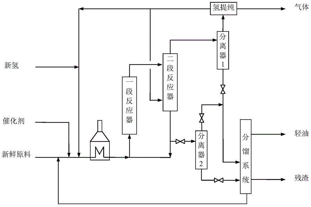
[0048] use figure 1 In the process shown, the raw material oil is the atmospheric residue of crude oil from a certain area of ​​Liaohe Oilfield, and its properties are listed in Table 1. The catalyst is a solid powder catalyst with a maximum particle size of 5 μm and an average particle size of 0.8 μm. The catalyst contains 90m% of ferrous sulfide and 10m% of molybdenum sulfide. Adopt two identical empty barrel reactors connected in series, the volume of the reactor is 500ml, the first reactor is operated according to the first reaction zone described above, and the second reactor is operated according to the second reaction zone described above , the specific operating conditions are listed in Table 2, and the product distribution obtained is listed in Table 3.

[0049] During the test, by measuring the pressure difference ΔP between the upper and lower parts of the reactor and the height difference ΔH between the upper and lower parts of the reactor, according to the compos...

Embodiment 2

[0065] The difference between this embodiment and Embodiment 1 is that the temperature of the first stage reactor is 435°C, and the operating temperature of the second reactor is 455°C. Other aspects not listed are all the same as Example 1. The resulting product distribution is listed in Table 5.

[0066] Table 5 Distribution of two-stage hydrocracking products in Example 2

[0067] Enter

Embodiment 3

[0069] The difference between this embodiment and embodiment 2 is that: the vacuum distillate oil and part of the vacuum residue (containing solid catalyst) obtained from the separation system are used as circulating materials, and the circulation ratio is 0.5; the amount of catalyst is reduced. Other aspects not listed are all the same as Example 2. The resulting product distribution is listed in Table 6.

[0070] Table 6 Distribution of two-stage hydrocracking products in Example 3

[0071] Enter

[0072] hydrogen


PUM


Abstract

The invention relates to a hydrocracking method for heavy oil. The method comprises the following steps that the heavy oil, hydrogen and a catalyst enter a first reaction zone, the mixture flow of the heavy oil, the hydrogen and the catalyst flows upwards in the first reaction zone and reacts under the condition of hydrocracking on a suspended bed; after the mixture flow flows out of the first reaction zone, the mixture flow is divided into gas phase flow and liquid phase flow by gas-liquid separation; the liquid phase flow enters a second reaction zone, flows downwards and is in counter-current contact and reacts with the nitrogen flowing upwards under the condition of hydrocracking on the suspended bed; after the liquid phase flow flows out of the second reaction zone, part or all of the liquid phase flow enters a separation system to carry out product separation. According to the hydrocracking method for the heavy oil, not only can the separation rate of the gas in the reactor be reduced, but also a hydrocracking effect of the heavy oil can be further improved.

Description

technical field [0001] The invention relates to a method for hydrocracking of heavy oil, in particular to a method for hydrocracking of heavy oil with two reaction zones with different operation modes. Background technique [0002] In the hydrogenation process of heavy oil such as petroleum heavy oil, coal tar, and shale oil, a large number of colloids, asphaltenes, metal ions, solid particles and other pollutants in the system directly affect the service life of the hydroconversion catalyst and the long-term performance of the device. Periodic operation, for this kind of raw material containing high pollutants, suspended bed hydrogenation is an ideal technology. The reaction conditions for suspension bed hydrogenation are generally: the reaction temperature in the reactor is 320-480°C, the reaction pressure is 8-25MPa, and the volume space velocity is 0.3-3h -1 , The volume ratio of hydrogen to oil is 500-2000. Suspension-bed hydrogenation catalysts can be divided into th...

Claims


Application Information

Patent Timeline
IPC IPC(8): C10G67/00
CPCC10G67/00
Inventor 何洪洋
Owner BLOOMING BEIJING TECH
Why Eureka
Try Eureka