Laser aided rock-breaking fixed gear drill bit

A laser-assisted, fixed-tooth technology, which is applied to drill bits, drilling equipment, earthwork drilling and mining, etc., can solve the problems that laser technology is not widely used, achieve the effect of destroying the overall strength, reducing the difficulty of rock breaking, and assisting rock breaking

Inactive Publication Date: 2015-04-29
CHINA PETROCHEMICAL CORP +1
View PDF5 Cites 14 Cited by
  • Summary
  • Abstract
  • Description
  • Claims
  • Application Information

AI Technical Summary

Problems solved by technology

The results of the US Federal Aviation Research Light Cutting Rock Test show that the high-energy focused radiation emitted by the laser can be used to cut deep and thin slits on various hard rocks, but the current laser technology is not widely used in oil drilling

Method used


Image

  • Laser aided rock-breaking fixed gear drill bit

Examples


Embodiment 1

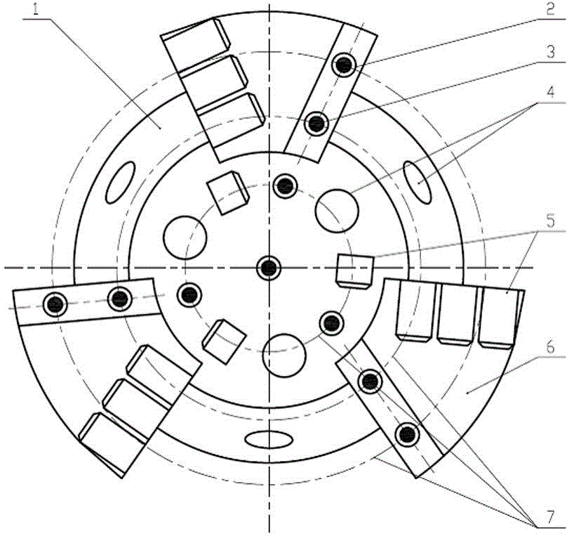
[0013] A fixed-tooth drill bit for laser-assisted rock breaking, mainly composed of a drill body 1, a mud channel 4, a cutting tooth 5, and a blade 6 arranged on the drill body 1, and an optical path channel 2 is also arranged on the drill body 1. A laser head 3 is installed at the end of the channel 2 .

Embodiment 2

[0015] A fixed-tooth drill bit for laser-assisted rock breaking, mainly composed of a drill body 1 and a mud channel 4, a cutting tooth 5 and a blade 6 arranged on the drill body 1, and an optical path channel 2 is also arranged on the drill body 1, and an optical path channel 2 is arranged on the optical path A laser head 3 is installed at the end of the channel 2 . The optical path channels 2 are multi-channel, and are installed on the drill body 1 in circular distribution with different radii around the axis of the drill body 1 . The optical path channel 2 and the mud channel 4 are distributed in isolation from each other along the radial direction.

Embodiment 3

[0017] see figure 1 , the laser-assisted rock-breaking fixed-tooth drill bit has three independent rock-breaking methods: hydraulic, mechanical, and laser, and has an optical path channel 2 independent of the mud channel 4; the optical path channel 2 is equipped with a laser head 3; the fixed-tooth drill bit adopts three blades, Leave as much room as possible on the drill bit to distribute the optical path channel 2; the drill bit adopts a larger-sized composite sheet with a simple envelope design; the distribution of the optical path channel 2 starts from the center of the end face of the drill bit, and gradually moves along the axis of the drill body 1 along the radial direction. Distributed outside, the 9 laser heads installed around naturally form three circles, which are three concentric circles from the top view of the drill bit, which we call the laser ring 7. The laser-assisted rock-breaking fixed-tooth drill bit adopts the strategy that the larger the radius of the l...


PUM


Abstract

The invention discloses a laser aided rock-breaking fixed gear drill bit. The laser aided rock-cracking fixed gear drill bit mainly comprises a drill bit body, a light path passage, a laser head, a mud passage, a cutting gear and a knife wing, wherein the drill bit body is also provided with the light path passage; the laser head is arranged on the end part of the light path passage. The drill bit has three independent rock-breaking ways, i.e. a hydraulic rock-breaking way, a mechanical rock-breaking way and a laser rock-breaking way, on the basis of the traditional mechanical rock-breaking way and hydraulic rock-breaking way, the laser aided rock-breaking way is added, and the light path passage independent of the mud passage is arranged. A rock layer is irradiated by laser emitted by the laser head arranged in the laser passage, and rocks are crushed, smelted or vaporized before being cut by the drill bit, so that the aims that the cutting difficulty of the drill bit is reduced, the drill bit is protected, the service life of the drill bit is prolonged, and the mechanical drilling speed of a ground layer which is difficultly drilled is increased are fulfilled.

Description

technical field [0001] The invention relates to the field of drilling bits, in particular to a fixed-tooth drill bit for laser-assisted rock breaking. Background technique [0002] Since the rotary drilling replaced the traditional Drilling Drilling in the early 20th century and realized the first innovation of oil drilling, it has been relying on high drilling pressure, high torque and high speed to increase the ROP, and the drilling method has not changed much. Today's vigorous development of new technologies has brought about the continuous emergence of new rock breaking methods, such as water jet devices, electron beams, cavitation jets, electric arcs, plasmas and lasers. In May 1960, C.M.Maman invented the world's first milliwatt-level ruby ​​crystal laser. In the following decades, laser technology has been applied in the fields of national defense engineering, information communication, material processing, biomedicine, food hygiene and transportation. It has been wi...

Claims


Application Information

Patent Timeline
Patent Type & Authority Applications(China)
IPC IPC(8): E21B10/42E21B7/00
CPCE21B10/42E21B7/00
Inventor 谢慧周燕罗熙陈志礼
Owner CHINA PETROCHEMICAL CORP
Why Eureka
Try Eureka