Mechanical arm modeling and solving method based on improvement of multi-body system transfer matrix

A transfer matrix, multi-body system technology, applied in special data processing applications, instruments, electrical digital data processing, etc., can solve problems such as difficult kinematics and dynamics unification

Inactive Publication Date: 2015-04-29
TIANJIN UNIVERSITY OF TECHNOLOGY
View PDF1 Cites 18 Cited by
  • Summary
  • Abstract
  • Description
  • Claims
  • Application Information

AI Technical Summary

Problems solved by technology

[0008] The purpose of the present invention is to solve the problem that the existing methods are difficult to unify the research of kinematics and dynamics in one mathematical description, and use the improved multi-body system discrete time transfer matrix method to establish a unified model of the dynamics of the plane manipulator , and propose an effective numerical solution method for system kinematics and dynamics

Method used


Image

  • Mechanical arm modeling and solving method based on improvement of multi-body system transfer matrix
  • Mechanical arm modeling and solving method based on improvement of multi-body system transfer matrix
  • Mechanical arm modeling and solving method based on improvement of multi-body system transfer matrix

Examples


Embodiment 1

[0065] Embodiment 1, mechanical arm dynamics modeling

[0066] In order to describe in detail the improvement of the multi-body system transfer matrix method of the present invention and its application to the technical method of modeling and solving the dynamics of the manipulator, the following is an example of a two-degree-of-freedom serial manipulator in planar motion. The specific steps are as follows:

[0067] 1. Disassemble the robotic arm system

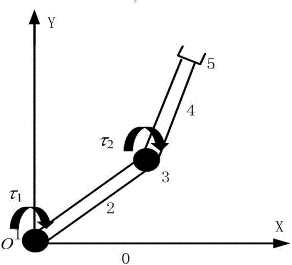
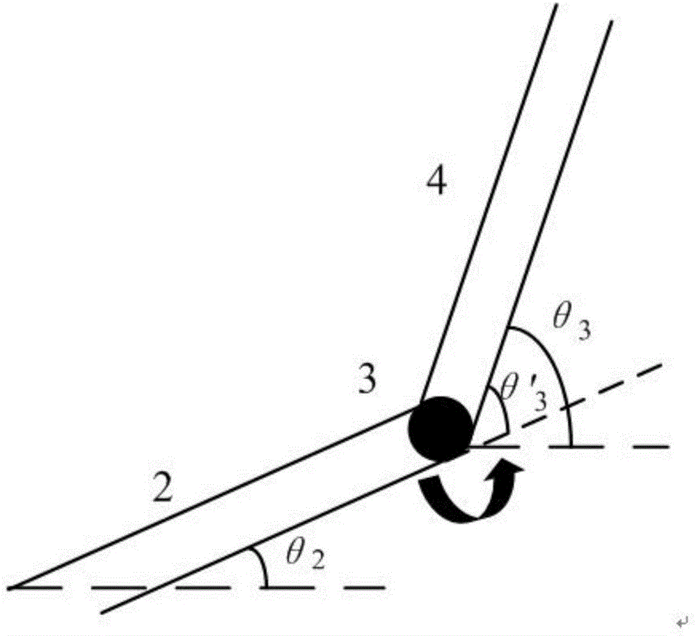
[0068] Such as figure 1 Shown is a two-degree-of-freedom planar motion manipulator. The rigid body system is decomposed, and the whole manipulator is a chain system composed of four planar rigid body elements with one end input and one end output. In the figure, number 0 represents the base, starting from the base, the first and third rigid bodies represent joints, the second and fourth rigid bodies represent rods, and the number 5 represents the end of the mechanical arm. According to the modeling idea of ​​discrete time t...

Embodiment 2

[0090] Embodiment 2, the solution of model

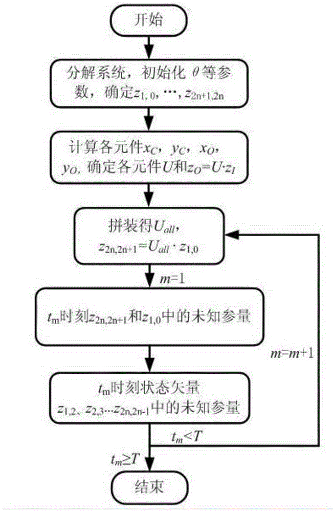
[0091] For a series multi-joint manipulator, there are two situations according to the kinematics law, one is to solve the terminal information with the known joint motion law, that is, forward kinematics solution; the other is to solve the joint information with the known end point motion law , belongs to the kinematics inverse solution problem. For the overall equation of dynamics of the two-degree-of-freedom manipulator shown in formula (5), the solution to any of the above-mentioned motion situations needs to set the boundary conditions of the overall equation according to the known and unknown conditions, and then through the iteration of the transfer matrix Get the unknown parameters of each state vector. These parameters contain all the information about the position and force of each joint and rod in the manipulator, so the solution of the two motion situations is the superposition of the kinematics problem and the inverse ...


PUM


Abstract

The invention discloses a mechanical arm modeling and solving method based on improvement of a multi-body system transfer matrix. The method is characterized in that a discrete time transfer matrix method of the multi-rigid-body system is improved according to the structure characteristics of a planar mechanical arm and the relation between motion transfer and force transfer, a unified model of an n-degree-of-freedom series mechanical arm is built, and kinematic and dynamic solving method and process of a system model is provided by setting the boundary condition according to the two acknowledged motion conditions between the joint space and the operation space of the mechanical arm. The method has the advantages of being flexile in modeling, small in calculation scale, capable of covering the kinematic and dynamic characteristics of the system and more effective compared with the traditional robot modeling method, showing the excellence of the new method, and achieving the aims of clear idea, simple programming and achievement easiness.

Description

technical field [0001] The invention relates to a modeling method and solving method of a mechanical arm based on an improved multi-body system transfer matrix. [0002] According to the structural characteristics of the planar manipulator, the relationship between motion transmission and force transmission, the present invention improves the discrete-time transfer matrix method of the multi-rigid body system, and proposes a unified model of n-joint series manipulators that covers system kinematics and dynamics features and its solution The method belongs to the technical field of articulated series robots. Background technique [0003] With the rapid development of science and technology, robots have been widely used in the fields of industrial automation production, medical treatment, military, semiconductor manufacturing and space exploration. The articulated serial robot is constructed by simulating the upper arm of a human being. It has the advantages of flexible movem...

Claims


Application Information

Patent Timeline
Patent Type & Authority Applications(China)
IPC IPC(8): G06F17/50
Inventor 陈炜李浩郭月
Owner TIANJIN UNIVERSITY OF TECHNOLOGY
Why Eureka
Try Eureka