Bored composite pile structure under karst cave/soil cave geological condition

A technology of geological conditions and composite piles, applied in the direction of foundation structure engineering, sheet pile walls, buildings, etc., can solve the problem of large concrete filling coefficient, achieve the effect of reducing the amount, reducing the filling coefficient, and reducing the filling coefficient

Active Publication Date: 2015-05-13
YUNNAN JIANTOU FOUND ENG CO LTD +1
View PDF6 Cites 17 Cited by
  • Summary
  • Abstract
  • Description
  • Claims
  • Application Information

AI Technical Summary

Problems solved by technology

[0009] The purpose of the present invention is to overcome the difficulties in the construction of bored piles under the geological conditions of karst caves/soil caves, and provide a method that can effectively solve the problem that the concrete filling coefficient is too large...

Method used


Image

  • Bored composite pile structure under karst cave/soil cave geological condition
  • Bored composite pile structure under karst cave/soil cave geological condition
  • Bored composite pile structure under karst cave/soil cave geological condition

Examples


Embodiment 1

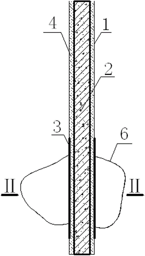
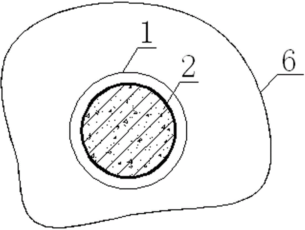
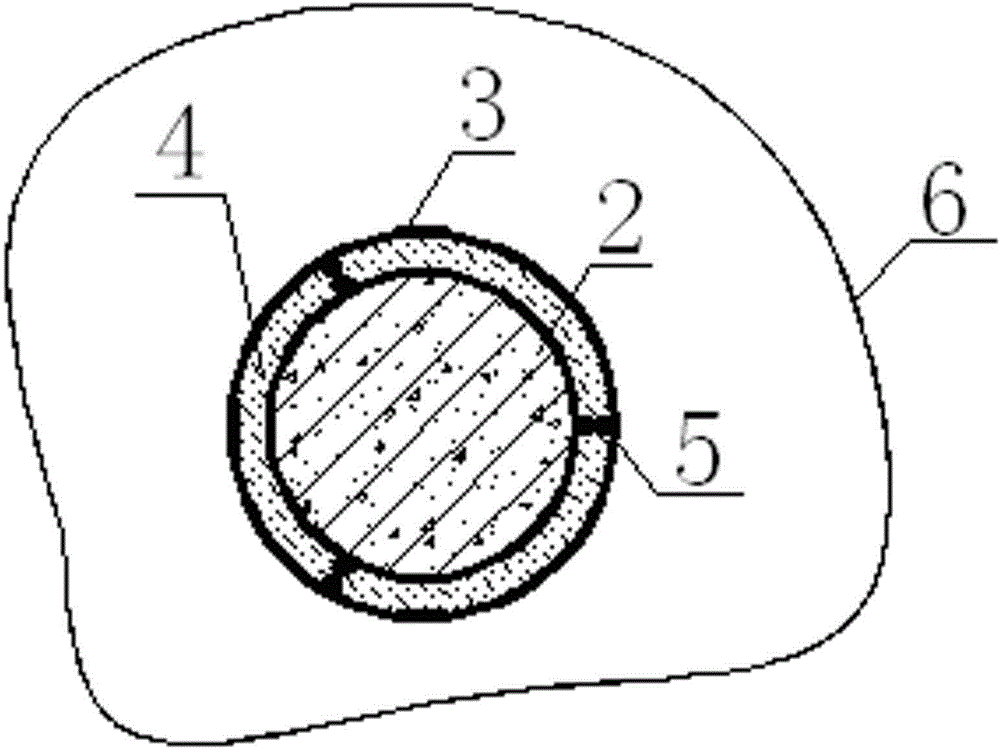
[0047] Example 1 :Such as figure 1 , 2 , 3, 4, and 5, prefabricate concrete square piles with a side length of 600mm at the construction site according to the bearing capacity requirements, and maintain them naturally. Cement, clay and water are used as raw materials to make clay cement slurry after mixing and filtering. Then drill a hole with a drilling machine, and the diameter of the hole is 200mm longer than the prefabricated pile side. After clearing the soil in the borehole, the prefabricated pile 2 is implanted into the borehole with a hoisting machine, and finally the clay cement slurry 4 is poured into the hole with a grouting pipe. Inject the gap between the reinforced concrete prefabricated pile and the borehole so that the side friction resistance of the prefabricated pile can be exerted. During operation, the center of the prefabricated pile should coincide with the center of the borehole to meet the design requirements.

Embodiment 2

[0048] Example 2 :Such as figure 1 , 2 , 3, 4, and 5, prefabricated prestressed concrete pipe piles with a diameter of 600mm and a wall thickness of 100mm were prefabricated at the construction site according to the design bearing capacity requirements, and naturally maintained. Then cement, clay and water are used as raw materials, and clay cement slurry is made after mixing and filtering according to national standards. Then use a drilling machine to form a hole. The diameter of the drilling hole is 200mm larger than that of the prefabricated pile. The gap between the piles can be used to make the side friction resistance of the pile body play a role. The center of the prefabricated pile should coincide with the center of the borehole.


PUM

PropertyMeasurementUnit
Diameteraaaaaaaaaa

Abstract

The invention discloses a bored composite pile structure under karst cave/soil cave geological conditions and belongs to the technical field of construction pile foundation engineering. The bored composite pile structure is composed of a borehole, a preformed pile, a protective cage, clay cement grout, a grouting pipe, karst cave (soil cave), protective cage longitudinal bars, protective cage hooping and geotechnical cloths. Constructions of a cast-in-situ bored pile under the karst cave/soil cave geological conditions are usually encountered with greater difficulties, and therefore the preformed pile can be implanted by way of drilling, and then the gap between the preformed pile and the borehole is filled with clay cement grout. Namely, first, a hole is drilled at a design pile position, and meanwhile the protective cage is fixed at a corresponding position, according to the height of a karst cave (soil cave) burial depth below the pile position, of the preformed pile, the protective cage is composed of the multiple protective cage longitudinal bars, the cage hooping located on the periphery of the protective cage longitudinal bars and taking a shape of a ring and the geotechnical cloths located on the periphery of the hooping; then, the preformed pile is lifted and placed into the borehole and the center of the preformed pile and the center of the borehole are ensured to coincide; finally, the clay cement grout is poured into the gap between the pile and the borehole through the grouting pipe and after the clay cement grout solidifies and stabilizes, the bored composite pile is formed.

Description

technical field [0001] The invention relates to a drilled composite pile structure under geological conditions of karst caves (soil caves), and belongs to the field of building pile foundation engineering. Background technique [0002] Karst caves refer to soluble rock formations, such as dolomite, limestone, dolomitic limestone, gypsum, rock salt, etc., after the chemical and mechanical action of water, grooves, cracks, cavities and surface depressions caused by the collapse of the top of the cavity, Depression and other phenomena and their functions. Soil cave is a geological phenomenon that the surface subsides due to the dissolution and erosion of the upper layer by surface water and groundwater. [0003] With the development of our country's social and economic construction and the acceleration of urbanization, the urban land is becoming increasingly tense, and cities are constantly asking for development space from the air and underground. As a result, the superstruc...

Claims


Application Information

Patent Timeline
IPC IPC(8): E02D5/50
Inventor 杨世相奚晶何雄兵吕家保
Owner YUNNAN JIANTOU FOUND ENG CO LTD
Why Eureka
Try Eureka