Ultra high speed laser driver circuit with bandwidth compensation and driver chip

A laser driver and ultra-high-speed technology, applied in lasers, laser parts, semiconductor lasers, etc., can solve the problems of increasing chip cost, occupying a large chip area, complex structure, etc., to eliminate the influence of parasitic capacitance and expand the bandwidth.

Active Publication Date: 2015-05-13
SOUTHEAST UNIV
View PDF5 Cites 18 Cited by
  • Summary
  • Abstract
  • Description
  • Claims
  • Application Information

AI Technical Summary

Problems solved by technology

Therefore, the design goal of the laser driver is to obtain high bandwidth and large output modulation swing performance. Most of the existing laser driver circuits with pre-emphasis function use inductive elements to expand the bandwidth, and the structure is relatively complex and requires a large amount of chip area. Increased cost of chip manufacturing

Method used


Image

  • Ultra high speed laser driver circuit with bandwidth compensation and driver chip
  • Ultra high speed laser driver circuit with bandwidth compensation and driver chip

Examples


Embodiment Construction

[0022] Below in conjunction with embodiment the present invention will be further described.

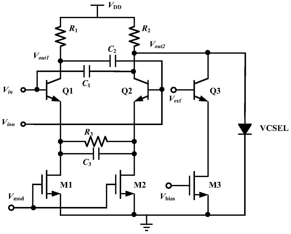
[0023] like figure 1 As shown, in the ultra-high-speed laser driver circuit with bandwidth compensation in this embodiment, the connection mode of each component is as follows:

[0024] The base of the NPN bipolar transistor Q1 is connected to the input voltage V in and capacitance C 1 The first terminal of the transistor Q1 is connected to the collector of the resistor R 1 The first terminal and the capacitor C 2 The first end of the transistor Q1, the emitter of the transistor Q1 is connected to the drain of the MOS transistor M1 on the one hand, and the resistor R is connected to the other. 3 The first terminal and the capacitor C 3 the first end of

[0025] The base of the NPN bipolar transistor Q2 is connected to the input voltage V inn and capacitance C 2The second terminal of the transistor Q2 is connected to the collector of the resistor R 2 The first terminal of the...


PUM


Abstract

The invention discloses an ultra high speed laser driver circuit with bandwidth compensation and a diver chip; the feedback circuit composed of two cross coupling capacitors and the capacitor and the resistor connected in a parallel mode is used for executing the laser driver bandwidth compensation. For two cross coupling capacitors, the stray capacitance between the base and the collector can be eliminated; for the feedback mode of one capacitor and one resistor, one zero point is generated for compensating the pole for realizing the bandwidth compensation; and the modulating current directly flows to the laser diode through the load resistor, so that the laser diode can obtain larger modulating current. The laser driver circuit and the driver chip having pre-emphasis function are simple in structure, high in bandwidth, large in modulating current and low in power consumption; the chip adopts the resistor and capacitor for expanding the bandwidth, the occupied area is small and the chip cost is reduced; the work speed is 40Gb/s through the 0.13 mum BiCMOS process certification and the output modulating current is greater than 10 mA.

Description

technical field [0001] The invention relates to a laser driver circuit at a transmitting end in an optical fiber communication system, in particular to a bandwidth-compensated ultra-high-speed laser driver circuit and a driver chip. Background technique [0002] Due to its large capacity and other characteristics, the optical fiber communication system has developed rapidly in network and multimedia communication. At the front end of the optical fiber is the light emitting end, which is composed of a multiplexer, a laser driver and a laser diode. The role of the optical transmitter is to multiplex multiple low-speed data signals into one high-speed signal through the multiplexer. After being amplified by the laser driver circuit, the laser diode is driven to emit light, converted into a high-speed optical signal, and transmitted through the optical fiber. Therefore, the design goal of the laser driver is to obtain high bandwidth and large output modulation swing performance...

Claims


Application Information

Patent Timeline
Patent Type & Authority Applications(China)
IPC IPC(8): H01S5/042
Inventor 陈莹梅王鹏霞王琼龚健伟
Owner SOUTHEAST UNIV
Why Eureka
Try Eureka