Flat-plate heat tube with nanometer structure

A flat heat pipe and nanostructure technology, applied in the direction of indirect heat exchangers, lighting and heating equipment, etc., can solve the problems of increased heat transfer resistance, large energy consumption, difficult control of sintering quality, etc., and achieve enhanced boiling heat transfer capacity , Improve heat transfer performance, speed up the effect of working medium circulation speed

Active Publication Date: 2015-05-20
GUANGDONG UNIV OF TECH
View PDF5 Cites 16 Cited by
  • Summary
  • Abstract
  • Description
  • Claims
  • Application Information

AI Technical Summary

Problems solved by technology

However, the return flow of the working medium in the existing flat heat pipe mainly depends on the capillary force provided by the liquid-absorbing core, and the capillary limit and boiling limit of heat transfer are relatively small. In addition, due to the existence of the liquid-absorbing core, the condensed liquid working medium close to the condensation surface cannot immediately Backflow floods the liquid-absorbent core near the condensation surface, which increases the heat transfer resistance. In addition, the sintered liquid-absorbent core structure itself consumes a lot of energy, and the sintering quality is difficult to control

Method used


Image

  • Flat-plate heat tube with nanometer structure
  • Flat-plate heat tube with nanometer structure

Examples


Embodiment Construction

[0019] The specific implementation manner of the present invention will be further described below in conjunction with the accompanying drawings.

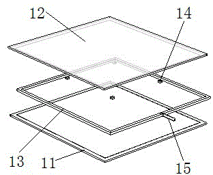
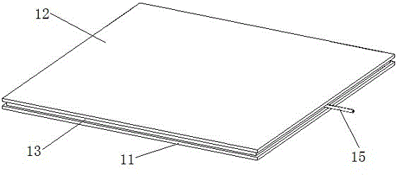
[0020] Such as figure 1 , figure 2 As shown, a nanostructured flat heat pipe of the present invention includes a bottom plate 11, a top plate 12, a support plate 13 between the top plate 12 and the bottom plate 11, and the bottom plate 11, the top plate 12, and the support plate 13 are sealed and connected to form a hollow airtight Cavity; the body of the bottom plate 11 as the evaporation surface of the flat heat pipe is a brass plate, and the inner surface of the bottom plate 11 is covered with a copper oxide film formed by electrochemical replacement with super-hydrophilic properties of nanostructure; as the condensation of the flat heat pipe The body of the top plate 12 is a brass plate. The inner surface of the bottom plate 12 is covered with a nanostructured electroplated nickel layer with superhydrophobic properties. The ...


PUM


Abstract

The invention discloses a flat-plate heat tube with a nanometer structure. The flat-plate heat tube with the nanometer structure comprises a bottom plate, a top plate and a supporting plate, wherein the supporting plate is positioned between the top plate and the bottom plate; the bottom plate, the top plate and the supporting plate are hermetically connected to one another to form a hollow closed cavity; a body of the bottom plate which serves as an evaporation surface of the flat-plate heat tube is a brass sheet; a copper oxide film which has a nanometer structure, has a super-hydrophilic property and is formed by electrochemical displacement covers the inner surface of the bottom plate; a body of the top plate which serves as a condensation surface of the flat-plate heat tube is a brass sheet; an electro-nickelling layer which has a nanometer structure and has a super-hydrophobic property covers the inner surface of the top plate; and small through holes are formed in a side surface of the supporting plate and are connected with capillary tubes. The evaporation surface and the condensation surface of the flat-plate heat tube are subjected to super-hydrophilic and super-hydrophobic surface modification, the evaporation speed and the condensation speed are increased, the heat exchange performance of an evaporation region and the heat exchange performance of a condensation region are improved, the thermal homogeneity is high, working medium is guided to return, and the working medium returning speed is increased, so that the whole heat exchange capability is improved.

Description

technical field [0001] The invention relates to heat dissipation technology of microelectronic devices, in particular to a nanostructure flat heat pipe for heat dissipation of microelectronic devices. Background technique [0002] With the rapid development of electronic packaging technology, the integration and performance of electronic chips continue to improve, resulting in a continuous increase in chip power. At present, the average heat flux density on the chip surface has exceeded 100W / cm2, and there is a tendency to continue to increase. At the same time, after the chip package is completed, there are generally "hot spots" with high local heat, which will lead to a sharp rise in the local temperature of the chip and affect the stability of the chip. [0003] Solutions to chip failure caused by temperature rise include not only conventional cooling methods such as air cooling, liquid cooling, and heat pipes, but also new cooling methods such as semiconductor cooling, ...

Claims


Application Information

Patent Timeline
IPC IPC(8): F28D15/04
CPCF28D15/0233F28D15/046
Inventor 王长宏黄炯桐
Owner GUANGDONG UNIV OF TECH
Why Eureka
Try Eureka