Super-resolution device and method based on pumping-probe technology

A super-resolution and probe technology, applied in the field of super-resolution, can solve the problems of slow imaging speed, strong optical power, and complex imaging system of STORM microscopy

Inactive Publication Date: 2015-05-20
ZHEJIANG UNIV
View PDF5 Cites 12 Cited by
  • Summary
  • Abstract
  • Description
  • Claims
  • Application Information

AI Technical Summary

Problems solved by technology

Among them, the resolution of STED microscopy is determined by the optical power of the added loss light. Therefore, when achieving high resolution, the required optical power is very strong, which easily leads to the bleaching of fluorescent molecules.
In addition, the system of STED microscopy is relatively complicated, and the cost is generally relatively high.
SIM microscopy does not require high optical power, but due

Method used


Image

  • Super-resolution device and method based on pumping-probe technology
  • Super-resolution device and method based on pumping-probe technology
  • Super-resolution device and method based on pumping-probe technology

Examples


Embodiment 1

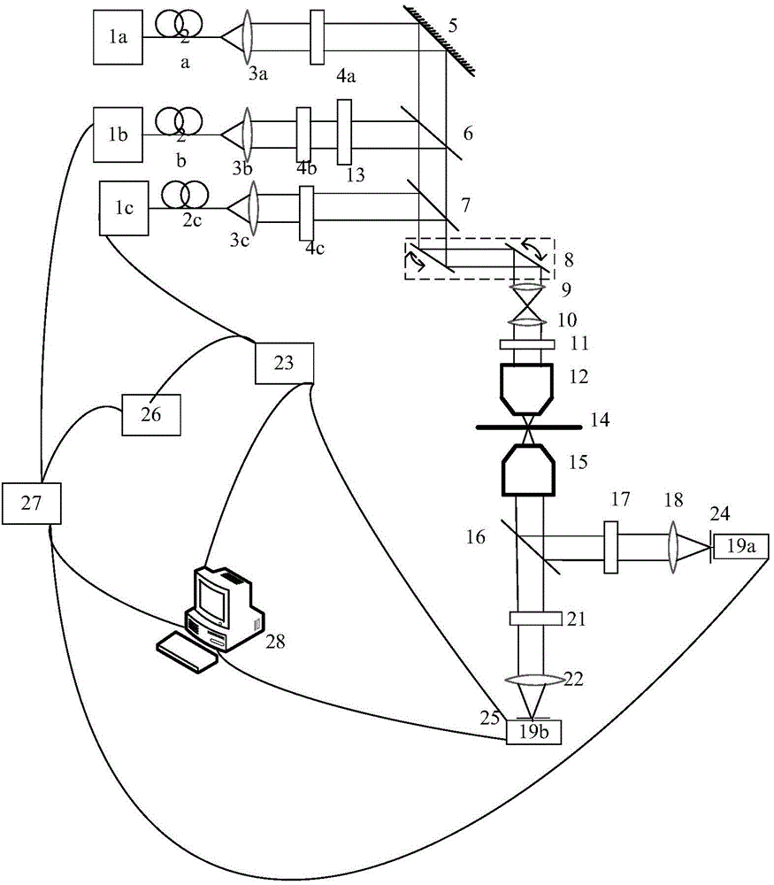
[0059] Such as figure 1 As shown, a super-resolution microscopy device, including: respectively emitting wavelength λ 1 , lambda 2 , lambda 3 Laser 1a, laser 1b and laser 1c, single-mode fiber 2a, single-mode fiber 2b, single-mode fiber 2c, collimator lens 3a, collimator lens 3b, collimator lens 3c, polarizer 4a, polarizer 4b, polarizer Polarizer 4c, reflector 5, dichroic mirror 6, dichroic mirror 7, scanning galvanometer system 8, scanning lens 9, field mirror 10, 1 / 4 wave plate 11, microscopic objective lens 12, microscopic objective lens 15, 0 ~2π vortex phase plate 13 (the vortex phase plate can also be replaced by a spatial light modulator SLM), light-transmitting sample stage 14, dichroic mirror 16, filter 17, filter 21, focusing lens 18, focusing lens 22, pinhole 24, pinhole 25, detector 19a, detector 19b, phase-locked loop 23, phase-locked loop 27, signal generator 26, computer 28.

[0060] Single-mode fiber 2a, single-mode fiber 2b, single-mode fiber 2c, collimato...

Embodiment 2

[0092] When lasers 1b, 1c emit wavelength λ 2 =λ 3 , in order to effectively separate the solid facula and the hollow facula, slightly modify the original device to adopt Figure 6 The device is carried out.

[0093] Such as Figure 6 The super-resolution microscopy device shown includes: respectively emitting wavelength λ 1 , lambda 2 =λ 3 Laser 1a, laser 1b, laser 1c, single-mode fiber 2a, single-mode fiber 2b, single-mode fiber 2c, collimator lens 3a, collimator lens 3b, collimator lens 3c, polarizer 4a, polarizer 4b, polarizer Polarizer 4c, reflecting mirror 5, dichroic mirror 6, scanning galvanometer system 8, scanning lens 9, field mirror 10, 1 / 4 wave plate 11, microscopic objective lens 12, microscopic objective lens 15, 0~2π vortex phase Plate 13 (can be replaced by a spatial light modulator), light-transmitting sample stage 14, optical filter 17, optical filter 21, reflector 29, focusing lens 18, focusing lens 22, pinhole 24, pinhole 25, detector 19a, a detecto...


PUM


Abstract

The invention discloses a super-resolution method based on a pumping-probe technology. The super-resolution method is characterized in that a first light beam irradiates a sample and the atoms of the sample are transitioned to an excited state, a second light beam forms hollow light spots on the sample after phase modulation and excites signal light, and a third light beam forms hollow light spots on the sample and excites signal light. The super-resolution method comprises the following steps: controlling the frequency of the third light beam to be V1, detecting the signal light with the frequency being V1 and obtaining a first signal light intensity I1(x, y); controlling the frequency of the second light beam to be V2, detecting the signal light with the frequency being V1 and obtaining a second signal light intensity I2(x, y); and calculating effective signal light intensity I (x, y) at all scanning points, wherein x and y are two-dimensional coordinates of the scanning points, thus obtaining a super-resolution microscopic image. The invention also discloses a super-resolution device based on a pumping-probe technology. The super-resolution method and the super-resolution device have the advantages that the imaging speed is high, differentiated images can be scanned simultaneously, and the stimulated radiation is faster than spontaneous radiation of the original method.

Description

technical field [0001] The invention belongs to the field of super-resolution, in particular to a fast pump-probe technology-based super-resolution microscopy method and device. Background technique [0002] Due to the effect of diffraction from the optical system, there is a limit to the resolution achievable by conventional far-field optical microscopy methods. According to Abbe's diffraction limit theory, the size of the spot formed by the beam focused by the microscope objective lens is expressed as Where λ is the operating wavelength of the microscope, and NA is the numerical aperture of the microscope objective used. Therefore, the limiting resolution of conventional far-field optical microscopes is generally limited to about half a wavelength. [0003] Pump-probe (Pump-probe) technology As a standard nonlinear measurement tool, the Pump-probe technology has existed for decades, and it is used to characterize the photoinduced optical change characteristics of the ex...

Claims


Application Information

Patent Timeline
IPC IPC(8): G01N21/63G01N21/64G02B21/36G02B21/06
Inventor 刘旭赵光远王轶凡匡翠方
Owner ZHEJIANG UNIV
Why Eureka
Try Eureka