
Planar optical waveguide and manufacturing method thereof

A planar optical waveguide and waveguide core technology, which is applied to optical waveguides, light guides, optics, etc., can solve the problems of increasing instability and process risk, difficulty in controlling birefringence effects, and increasing production costs and risks. Solve the effect of the uniformity of core layer production, solve the accumulation of three image transfer errors, and improve the production efficiency

Active Publication Date: 2015-05-20
广东瑞芯源技术有限公司
View PDF4 Cites 30 Cited by
  • Summary
  • Abstract
  • Description
  • Claims
  • Application Information

AI Technical Summary

Problems solved by technology

In the second process difficulty, for the production of the metal mask, the side wall angle of the photomask and the bifurcation error of the waveguide will be transmitted to the side wall angle of the metal mask and other changes, and the accumulation of errors will affect the precise transfer of the image. Dry etching requires expensive ICP / RIE etching equipment, uses highly toxic chlorine gas, increases production costs and risks, and has low efficiency
However, this method additionally uses phosphine, a highly toxic gas. Phosphorus is relatively easy to be affected by moisture, and the thermal expansion coefficient of the material is large. In addition, the upper and lower claddings are made of different quartz glass materials, so the thermal expansion coefficient is very different, and the birefringence effect is difficult to control. This increases the The instability of the product and the danger of the process
[0029] Usually, the thickness of one-time PECVD deposition is not more than 6 microns, and the thickness of the upper cladding layer is required to be about 20 microns. Using PECVD alone to make the upper cladding layer requires multiple depositions and high-temperature annealing treatments, which has low efficiency and high production costs.
[0030] The FHD process can deposit more than 20 microns of cladding at one time, which has the advantages of high efficiency and low production cost. However, in terms of the refractive index control of the cladding, it is difficult to accurately achieve a uniform relative refractive index difference Δ, which will affect the final product. Yield rate, especially for arrayed waveguide grating (AWG) production, so the industry has generally seldom used

Method used


Image

  • Planar optical waveguide and manufacturing method thereof
  • Planar optical waveguide and manufacturing method thereof
  • Planar optical waveguide and manufacturing method thereof

Examples


preparation example Construction

[0070] The present invention also provides a method for preparing a planar optical waveguide, comprising the following steps:

[0071] (1) forming a first portion of the isolation layer on the lower cladding layer;

[0072] (2) forming a core layer on the first portion of the isolation layer;

[0073] (3) etching the core layer to form the waveguide core layer with a preset structure;

[0074] (4) forming a second part of the isolation layer on the waveguide core layer and the first part of the isolation layer, the second part of the isolation layer completely fills the gap of the preset structure, and the first part of the isolation layer A part and a second part form the isolation layer and completely cover the waveguide core layer;

[0075] (5) The upper cladding layer is formed on the second portion of the isolation layer.

[0076] In some preferred embodiments, one or any combination of the following conditions may be preferred:

[0077] Described step (3) comprises t...

Embodiment 1

[0090] The preparation method of the planar optical waveguide comprises the following steps:

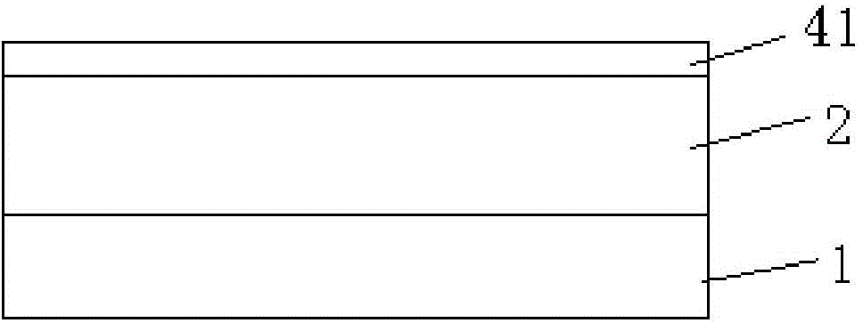
[0091] (1) The lower cladding layer 2 is formed on the substrate 1, the material of the substrate 1 is Si, and the material of the lower cladding layer 2 is SiO 2 ,Such as Figure 1a shown.

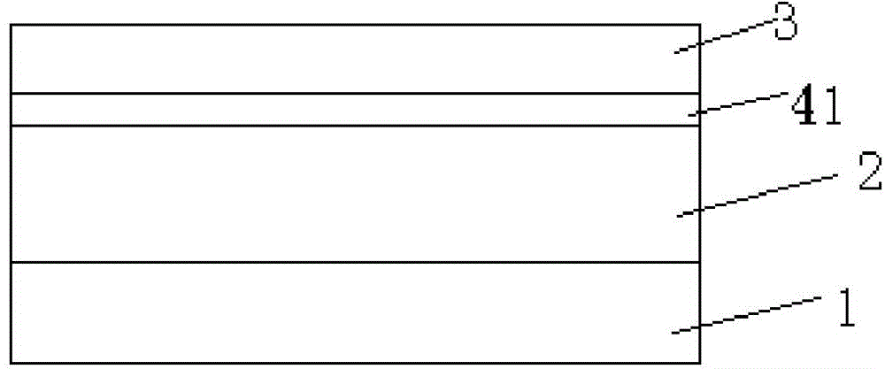
[0092] (2) Using plasma enhanced chemical vapor deposition (Plasma Enhanced Chemical Vapor Deposition, PECVD) process, the growth temperature is 320 ° C, the gas flow ratio: 10% (volume fraction) GeH 4 :C 2 f 6 :SiH 4 :N 2 O is 20:10:17:2000sccm, the RF input power is 700W, and the deposition chamber pressure is 380mTorr, deposit for 10 minutes, and then perform high-temperature annealing to form the first part of the isolation layer 4 with a thickness of 3 μm on the lower cladding layer 2 41. The process conditions for high-temperature annealing treatment are: in an atmosphere of oxygen and inert gas (volume ratio: 1:6), heat up for 100 minutes, keep the temperature at 950°C for 20 minute...


PUM

PropertyMeasurementUnit
Thicknessaaaaaaaaaa

Abstract

The invention discloses a planar optical waveguide and a manufacturing method thereof. The planar optical waveguide comprises a lower cladding, a waveguide core layer, an isolation layer and an upper cladding; the refractive index of the upper cladding is equal to that of the lower cladding and is higher than that of the isolation layer; the isolation layer is formed on the lower cladding; the waveguide core layer is packaged completely in the isolation layer; the upper cladding is formed on the isolation layer. The refractive index distribution of the planar optical waveguide is optimized, the loss of a device is reduced, and the 1250-1650 full band width performance can be realized more easily.

Description

technical field [0001] The invention relates to the field of semiconductors, in particular to a planar optical waveguide and a preparation method thereof. Background technique [0002] In the field of optical technology, various types of optical components in a single form are currently on the road to integrated optics. Optical modules are integrated on wafers to form basic components of integrated optical circuits, which helps to integrate optical communication components and reduce their volume. , Reduce the number of packages, have the advantages of large-scale production, low cost, high performance, high-density device integration, etc., and are a necessary part of the optical fiber communication system. [0003] The so-called planar lightwave circuit (PLC for short) means that the optical waveguide is located in a plane. Like the concept of an IC chip, a planar optical waveguide is an optical device technology that uses semiconductor technology to integrate optical com...

Claims


Application Information

Patent Timeline
IPC IPC(8): G02B6/122G02B6/13
CPCG02B6/122G02B6/13
Inventor 林升德吴金东胡海鑫
Owner 广东瑞芯源技术有限公司
Learn More