Reactor claw-link mechanism and manufacturing method thereof

A technology of a connecting rod mechanism and a manufacturing method, which are applied in the field of a reactor hook connecting rod mechanism and its manufacturing, can solve the problems of easy occurrence of pores and cracks, high scrap rate, poor forming effect, etc. The effect of easy welding and high product qualification rate

Inactive Publication Date: 2015-05-20
李泽文 +1
View PDF7 Cites 6 Cited by
  • Summary
  • Abstract
  • Description
  • Claims
  • Application Information

AI Technical Summary

Problems solved by technology

[0005] 1) The cobalt-based alloy surfacing welding hook and claw linkage mechanism has good wear resistance and impact toughness, but the surfacing process is difficult and prone to pores and cracks, so the scrap rate is high;
[0006] 2) The overall cobalt-based alloy casting can effectively ensure the hardness and wear resistance of the mating surface of the parts, but the toughness of the core of the parts is insufficient, and the impact resistance and wear resistance are worse than those of oxyacetylene surfacing parts;
[0007] 3) Both cobalt-based alloy surfacing and integral casting contain cobalt, which has adverse effects on refueling and decommissioning
However, this kind of surfacing welding is extremely difficult, and the forming effect of the surfacing welding process is poor, and it is easy to produce pores and cracks

Method used


Image

  • Reactor claw-link mechanism and manufacturing method thereof
  • Reactor claw-link mechanism and manufacturing method thereof
  • Reactor claw-link mechanism and manufacturing method thereof

Examples


Embodiment 1

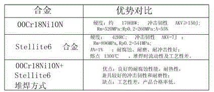
[0047] Such as figure 1 , figure 2 with Figure 5 As shown, the application provides a reactor claw 1 link 2 mechanism, including claw 1, connecting rod 2 and a pin for pin connection between claw 1 and connecting rod 2, the surface of the claw 1 is set There is a tooth surface, the claw 1 and the connecting rod 2 are respectively provided with a claw hole 11 and a connecting rod hole 21 for the pin connection of the two, and the number of the claw hole 11 and the connecting rod hole 21 is more than one, and the tooth surface Nickel-based alloy layer 3 is provided on the surface of the hook hole 11 and the inner wall surface of the connecting rod hole 21 .

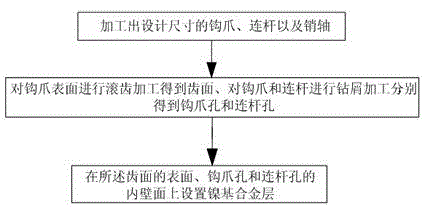
[0048] The present invention also provides a method for manufacturing the hook 1 connecting rod 2 mechanism of the reactor. This method is used to manufacture the above-mentioned hook 1 connecting rod 2 mechanism. The method includes processing the hook 1, the connecting rod 2 and the designed size The pin shaft, hobbi...

Embodiment 2

[0058] The present embodiment is further limited on the basis of embodiment 1, as Figure 2 to Figure 4 , Figure 7 to Figure 10 As shown, a method for manufacturing a reactor hook 1 connecting rod 2 mechanism includes a step of laying a nickel-based alloy layer 3, and the laying step is on the surface of the tooth surface, the inner wall surface of the hook hole 11 and the connecting rod hole 21 Nickel-based alloy layer 3 is surfacing on top.

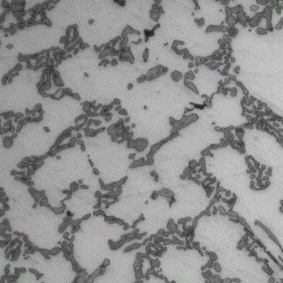
[0059] As can be seen from Example 1, the melting point of the nickel-based alloy is low, so that the nickel-based alloy layer 3 is well combined with the base of the claw 1 connecting rod 2 mechanism, so that the nickel-based alloy layer 3 and the claw 1 connecting rod 2 mechanism The joint surface of the two substrates can withstand the shear stress applied on the joint surface generated by the claw 1 connecting rod 2 mechanism during the working process. In this embodiment, the nickel-based alloy layer is selected in the form of su...

Embodiment 3

[0079] The present embodiment is further limited on the basis of embodiment 1 or 2, as Figure 5 with Image 6 As shown, this embodiment further limits the mechanism of the reactor claw 1 connecting rod 2. In order to prevent the nickel-based alloy layer 3 on the connecting rod hole 21 and the hook hole 11 from falling off as a whole during use, the connecting rod hole 21 and claw hole 11 are concentric different-diameter holes, and the minimum diameter points of connecting rod hole 21 and claw hole 11 are all located between respective two ends. The connecting rod hole 21 and the claw hole 11 of the above structure can prevent the nickel-based alloy layer 3 from moving axially along the connecting rod hole 21 or the claw hole 11 even after the nickel-based alloy layer 3 and the base layer fall off.

[0080] In order to facilitate the processing of the connecting rod hole 21 and the hook hole 11 in the above form, as a preferred structure, the connecting rod hole 21 and the h...


PUM


Abstract

The invention discloses a reactor claw-link mechanism and a manufacturing method thereof. The reactor claw-link mechanism comprises a claw, a link and a pin shaft, wherein the claw has a toothed surface; more than one claw hole and more than one link holes for pin connection of the claw and the link are formed in the claw and the link respectively; and nickel base alloy layers are arranged on the toothed surface, the inner wall surfaces of the claw holes and the inner wall surfaces of the link holes. The manufacturing method of the reactor claw-link mechanism comprises the following steps: processing the claw, the link and the pin shaft in design sizes, hobbing or turning the surface of the claw to obtain the toothed surface, drilling the claw holes and the link holes in the claw and the link respectively, and laying the nickel base alloy layers on the toothed surface, the inner wall surfaces of the claw holes and the inner wall surfaces of the link holes. Through the manufacturing method, the reactor claw-link mechanism with favorable corrosion resistance, abrasion resistance, impact resistance and manufacturability can be manufactured. The invention provides a corresponding processing method.

Description

technical field [0001] The invention relates to a part for a nuclear reactor and a processing technology of the part, in particular to a reactor claw linkage mechanism and a manufacturing method thereof. Background technique [0002] The step-by-step magnetic lifting control rod drive mechanism is a type of control rod drive mechanism mainly used in pressurized water reactor nuclear power plants. The claw link mechanism parts are used as the executive parts of the main action of the control rod drive mechanism, and the quality assurance level is Q1. , the quality of the parts directly determines the overall quality of the control rod drive mechanism. [0003] The function of the claw link mechanism is to drive the drive rod to move up and down through the engagement of the claw tooth surface with the drive rod ring groove, thereby driving the reactor control rod to move up and down to achieve the purpose of adjusting the power of the reactor and shutting down the reactor...

Claims


Application Information

Patent Timeline
Patent Type & Authority Applications(China)
IPC IPC(8): G21C7/14G21C21/18
CPCG21C7/14G21C21/18Y02E30/30
Inventor 李泽文刘霞
Owner 李泽文
Why Eureka
Try Eureka