Flying body with curved-surface micro groove structures and manufacturing method of flying body

A manufacturing method and micro-groove technology, applied in the direction of aircraft control, manufacturing tools, and affecting the air flow flowing through the aircraft surface, etc., can solve the problems of difficult precision machining of curved surfaces, failure to process microstructured curved surfaces, etc., and achieve enhanced Radar scattering capability, improved flight stability, and smooth bottom contour effects

Inactive Publication Date: 2015-05-27
SOUTH CHINA UNIV OF TECH
View PDF4 Cites 10 Cited by
  • Summary
  • Abstract
  • Description
  • Claims
  • Application Information

AI Technical Summary

Problems solved by technology

However, it is very difficult to precisely process the curved surface of hard and brittle materials. The commonly used laser processing and etching processing have not yet been able to process large-area and high-precision microstructure curved surfaces.
The surface material of the flying body is required to be relatively hard, and the flying body with a curved micro-groove structure has not been reported yet

Method used


Image

  • Flying body with curved-surface micro groove structures and manufacturing method of flying body
  • Flying body with curved-surface micro groove structures and manufacturing method of flying body
  • Flying body with curved-surface micro groove structures and manufacturing method of flying body

Examples


Embodiment 1

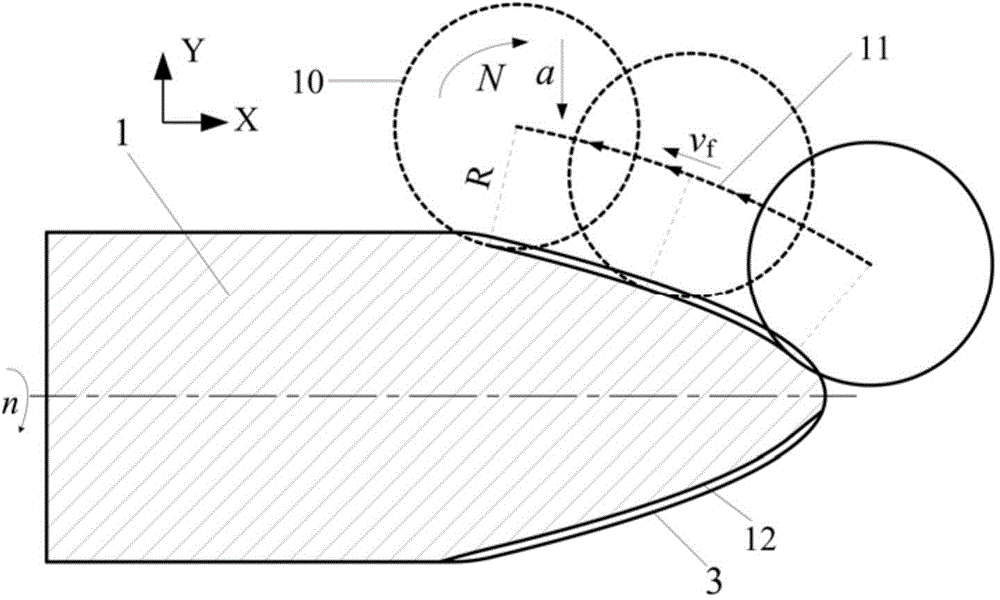
[0036]A CNC precision grinder (SMRART B818) was used to process ceramic rods, and the cylindrical ceramic rod was fixed on a Michelin three-jaw grinder (MCL-550) and rotated accordingly. The rotation speed of the flying body was n=500 rpm, and the diamond grinding wheel was fixed on on the wheel shaft. The coarse-grained diamond grinding wheel 2 for processing flying objects 1 has a diameter of 160 millimeters and a thickness of 10 millimeters, and is composed of diamond abrasives and bronze bonding agents. The diamond abrasive grain size is 120 meshes; the fine-grained diamond grinding wheel 7 for processing smooth curved surface flying objects Its diameter is 150 millimeters, thickness is 4 millimeters, is made up of diamond abrasive grain and resin bond, and diamond abrasive grain size is 3000 meshes; The diameter of the diamond grinding wheel 9 of processing the V tip of the smooth curved surface flying body with micro-groove structure is 160 millimeters , the thickness is...

Embodiment 2

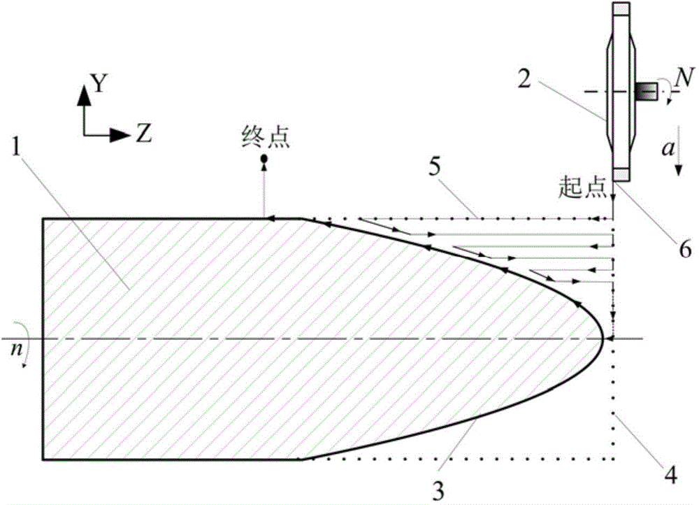
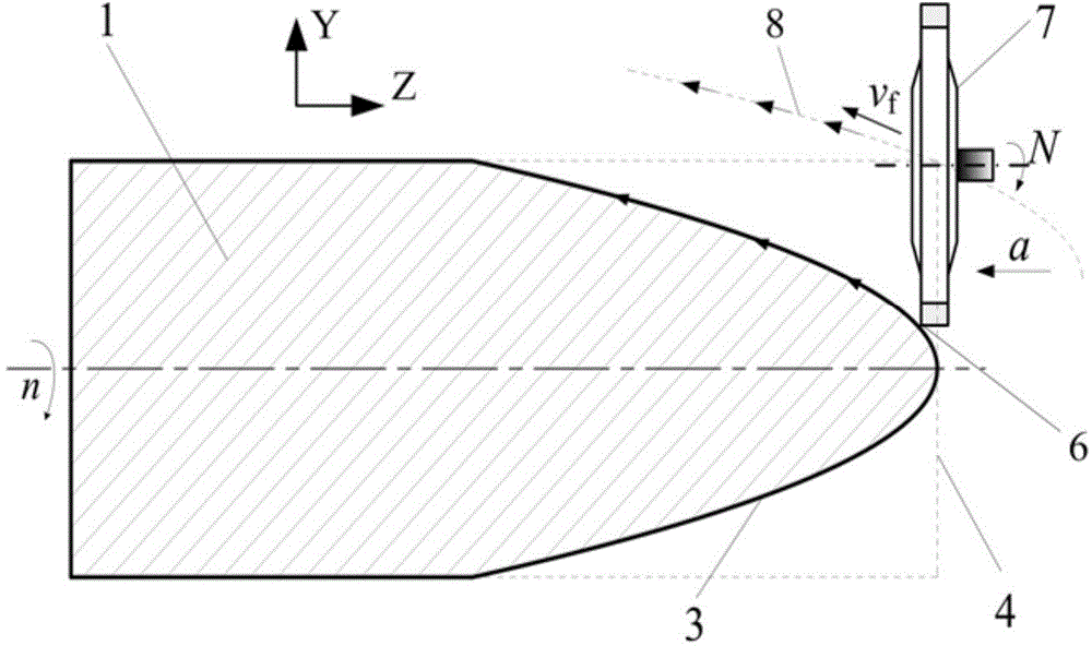
[0040] First, the axial direction of the ceramic rod is consistent with the axial direction of the grinding wheel. On the vertical section of the workpiece axial direction, the grinding path 5 of the ring end face corner 6 of the diamond grinding wheel 2 is used to adopt the layered feed (the grinding path 5 is Along the axial direction of the ceramic rod, according to the set CNC linear reciprocating path layered feeding (reciprocating broken line) for rough grinding of ceramics, the flying body is processed from the rough contour 4 to the curved surface contour 3, and the rough curved surface is processed. Body 1 (eg figure 1 shown), grinding wheel speed N=2500 rpm, feed speed v f =10 mm / min, depth of feed a=30 microns; Then, in the same orientation, utilize diamond emery wheel 7 to grind path 8 (parabolic track, its equation is z=y 2 / 7, z is the abscissa value (along the axial direction of the flying body) of the curved surface profile of the flying body head, and y is th...


PUM


Abstract

The invention discloses a flying body with curved-surface micro groove structures and a manufacturing method of the flying body. The flying body comprises a cylinder and a conical head, wherein multiple micro grooves are uniformly distributed at intervals along the axial section of the curved surface of the conical head, and the curved surface is a two-dimensional rotating surface in a parabolic surface or an elliptical surface. During machining, the manufacturing method comprises the steps of firstly machining a cylindrical material into the flying body which is provided with the conical head and has a rough curved surface with a curved surface profile; then machining the rough curved surface into a smooth curved surface along the curved surface profile by utilizing a corner of the annular end surface of a fine-grained diamond grinding wheel; finally axially steering the grinding wheel, enabling the grinding wheel to be vertical to a workpiece rotating shaft or to be in a certain inclination angle relative to the workpiece rotating shaft, enabling a workpiece to be fixed, and carrying out radial feeding along the radial direction of the smooth curved surface profile by utilizing a V-shaped pointed end of the diamond grinding wheel in high-speed rotation so as to machine the micro grooves in the curved surface. According to the manufacturing method disclosed by the invention, the smooth curved surface with the regular and controllable micro groove structures is machined on the flying body, the air resistance of the flying body can be reduced, the laser scattering can be enhanced, and resistance reduction and invisibility of flying can be finally realized.

Description

technical field [0001] The invention relates to the technical field of fine and precise manufacturing of hard and brittle components, in particular to a flying body with a curved micro-groove structure and a manufacturing method thereof. Background technique [0002] Hard and brittle materials such as ceramics, glass, and cemented carbide are widely used in industry, automobile manufacturing, and aerospace. For example, industrial micro-drills need to process spiral micro-grooves; in the field of tribology, micro-grooves are processed on the working surface of the engine cylinder liner to store lubricating oil and generate a fluid lubricating film, thereby improving the lubrication between the cylinder liner and the piston. Reduce component wear and extend component life; in the field of optical applications, micron-scale micro-groove arrays can be processed on the surface of quartz substrates to achieve adaptive positioning of optical fibers and reduce packaging costs for o...

Claims


Application Information

Patent Timeline
Patent Type & Authority Applications(China)
IPC IPC(8): B24B19/02B24B19/22B64C21/00
CPCB24B19/02B24B19/22B64C21/00
Inventor 谢晋鲁艳军李青罗敏健杨林丰
Owner SOUTH CHINA UNIV OF TECH
Why Eureka
Try Eureka