Waste water treatment system
A wastewater treatment and wastewater treatment system technology, applied in water/sewage treatment, water/sewage multi-stage treatment, degassed water/sewage treatment, etc., can solve the problems of cost increase, and achieve the purpose of preventing the increase of operating costs, low cost, etc. cost, effect of preventing oversizing
- Summary
- Abstract
- Description
- Claims
- Application Information
AI Technical Summary
Problems solved by technology
Method used
Image
Examples
Embodiment approach 1
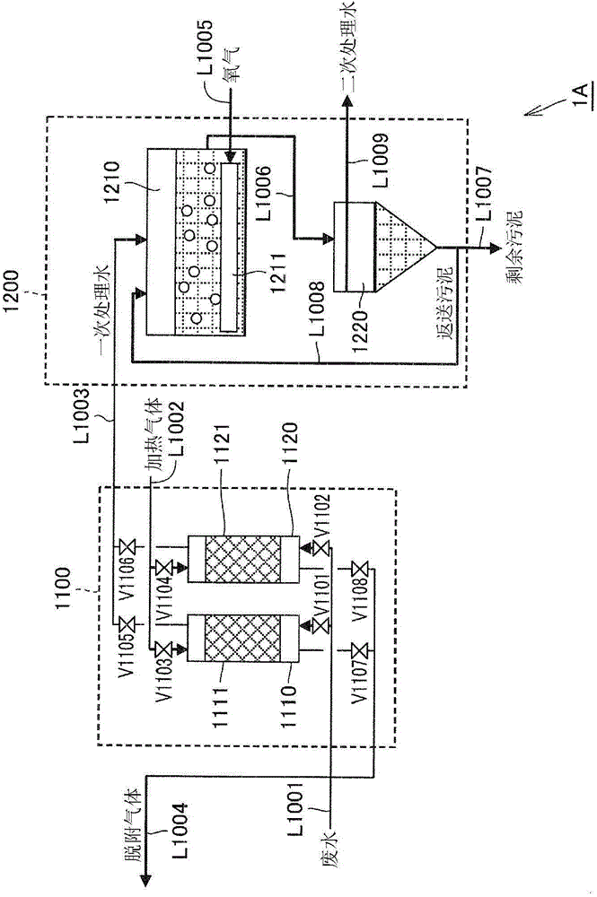
[0076] figure 1 It is a system configuration diagram of the wastewater treatment system according to Embodiment 1 of the present invention. Below, refer to the figure 1 The structure of the waste water treatment system 1A of this embodiment is demonstrated.
[0077] Wastewater Treatment System 1A
[0078] Such as figure 1 As shown, the wastewater treatment system 1A of this embodiment mainly includes a wastewater treatment device 1100 and an activated sludge treatment device 1200 .
[0079] Wastewater treatment plant 1100
[0080] The waste water treatment apparatus 1100 has the 1st treatment tank 1110 which accommodated the adsorption element 1111, and the 2nd treatment tank 1120 which accommodated the adsorption element 1121. The adsorption elements 1111 and 1121 adsorb organic compounds contained in the wastewater by contacting the wastewater containing the organic compounds.
[0081] That is, in the wastewater treatment apparatus 1100, the wastewater is supplied ...
Embodiment approach 2
[0126] Figure 4 It is a schematic diagram which shows the structure of the waste water treatment system of Embodiment 2 of this invention. In addition, in Figure 4 In the figure, the illustration of the same part as the waste water treatment system 1A of Embodiment 1 of this invention mentioned above is abbreviate|omitted. Below, refer to the Figure 4 The structure of the waste water treatment system 1B of this embodiment is demonstrated.
[0127] Wastewater Treatment System 1B
[0128] Such as Figure 4 As shown, the wastewater treatment system 1B of this embodiment differs from the wastewater treatment system 1A of Embodiment 1 of the present invention described above in the structure of the wastewater treatment device 1100 .
[0129] In the waste water treatment system 1B of this embodiment, the piping line L1010 for introducing gas to the waste water treatment device 1100 and the piping for introducing heating gas are connected to the piping line L1002 for introd...
Embodiment approach 3
[0137] Figure 5 It is a schematic diagram which shows the structure of the waste water treatment system of Embodiment 3 of this invention. Below, refer to the Figure 5 The structure of the waste water treatment system 1C of this embodiment is demonstrated.
[0138] Wastewater Treatment System 1C
[0139] Such as Figure 5 As shown, the wastewater treatment system 1C of this embodiment mainly includes a wastewater treatment device 1100 , an activated sludge treatment device 1200 and a combustion device 1300 .
[0140] The combustion device 1300 is a device for combusting and oxidatively decomposing the desorbed gas discharged from the waste water treatment device 1100, and the combustion device 1300 is connected to piping lines L1004, L1013, L1014, and L1015. The combustion device 1300 has a heat exchanger 1310 and a heating furnace 1320 . The heat exchanger 1310 is used to preheat the desorbed gas introduced into the heating furnace 1320 , and the heating furnace 1320...
PUM
| Property | Measurement | Unit |
|---|---|---|
| specific surface area | aaaaa | aaaaa |
| specific surface area | aaaaa | aaaaa |
| clearance rate | aaaaa | aaaaa |
Abstract
Description
Claims
Application Information
 - R&D
- Intellectual Property
- Life Sciences
- Materials
- Tech Scout
- Unparalleled Data Quality
- Higher Quality Content
- 60% Fewer Hallucinations
Browse by: Latest US Patents, China's latest patents, Technical Efficacy Thesaurus, Application Domain, Technology Topic, Popular Technical Reports.
© 2025 PatSnap. All rights reserved.Legal|Privacy policy|Modern Slavery Act Transparency Statement|Sitemap|About US| Contact US: help@patsnap.com


