
Automatic fuel gas flow control system for wire-drawing and filling-sealing machine

An automatic control system and combustion gas technology, applied in the directions of burners, combustion methods, combustion types, etc., can solve problems such as the inability to guarantee the stability and reliability of the fire, the influence of the qualified rate of product sealing, and the heavy workload of operators. Automatic and precise control of combustion gas flow, improve sealing qualification rate and finished product quality, and avoid the effect of bottle explosion

Active Publication Date: 2015-05-27
TRUKING TECH LTD
View PDF7 Cites 0 Cited by
  • Summary
  • Abstract
  • Description
  • Claims
  • Application Information

AI Technical Summary

Problems solved by technology

The above method of controlling the combustion gas supply through manual adjustment has the following disadvantages: when the machine operating speed and pressure change, in order to achieve better product quality, the combustion gas supply must be adjusted to ensure the combustion effect
If manual adjustment is used, there are problems of frequent manual adjustment and heavy workload of the operator; and because the whole adjustment process is completely dependent on the experience of the operator, and the degree of fire is only judged by the naked eye, and then the flow of gas gas is adjusted.
Manual adjustment cannot guarantee the stability and reliability of the fire, and in the debugging process, it will cause a lot of waste due to lack of experience or debugging errors
Obviously, this will have a negative impact on the pass rate of product sealing
Moreover, the above-mentioned operation mode is also prone to misoperation, resulting in an explosion and endangering human safety.

Method used


Image

  • Automatic fuel gas flow control system for wire-drawing and filling-sealing machine
  • Automatic fuel gas flow control system for wire-drawing and filling-sealing machine

Examples


Embodiment Construction

[0023] The present invention will be further described in detail below in conjunction with the accompanying drawings and specific embodiments.

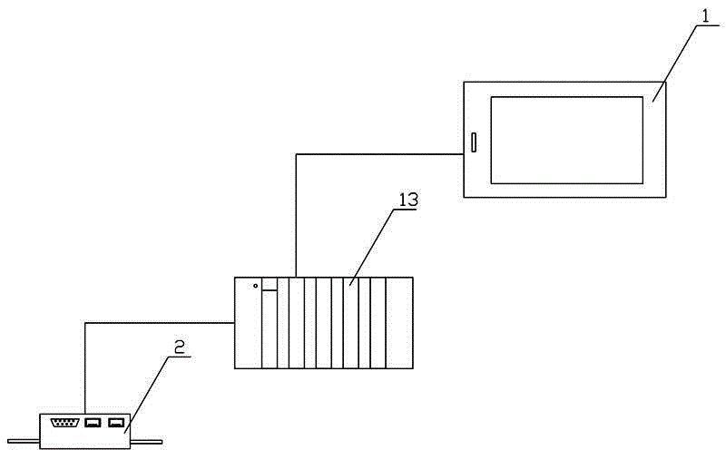
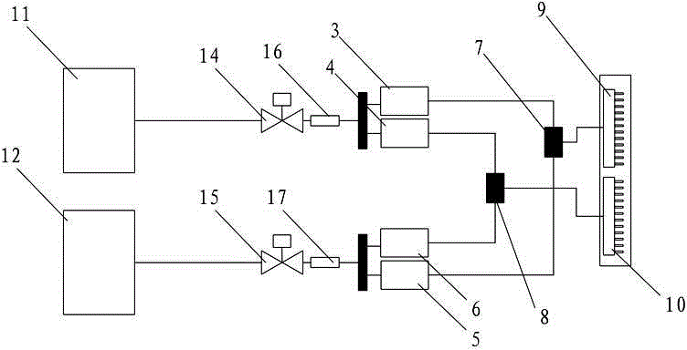
[0024] Such as figure 1 with figure 2 As shown, the combustion gas flow automatic control system for the wire drawing filling and sealing machine of the present invention includes a control assembly 1 and a flow proportional control valve assembly 2, and the input ends of the flow proportional control valve assembly 2 are respectively connected to the assisted gas source (such as: oxygen The gas source 11) and the gas source 12 are connected, the output end of the flow proportional control valve assembly 2 is connected with the burner assembly, the control end of the flow proportional control valve assembly 2 is connected with the control assembly 1 and receives the control signal of the control assembly 1 To adjust the mixing ratio and / or flow of combustion gas.

[0025] In a specific application example, the control component 1 o...


PUM


Abstract

The invention discloses an automatic fuel gas flow control system for a wire-drawing and filling-sealing machine. The automatic fuel gas flow control system comprises a control component and a flow proportional control valve component, wherein an input end of the flow proportional control valve component is communicated with a combustion-supporting gas source and a fuel gas source respectively; an output end of the flow proportional control valve component is connected with a combustion nozzle component; a control end of the flow proportional control valve component is connected with the control component and used for receiving a control signal of the control component to regulate a mixing proportion and / or the flow of the fuel gas. The automatic fuel gas flow control system has the advantages of being capable of increasing the automatic level, improving a control effect and the like.

Description

technical field [0001] The invention mainly relates to the field of food and medicine packaging equipment, in particular to an automatic combustion gas flow control system suitable for wire drawing filling and sealing machines. Background technique [0002] In the fields of medicine, food, chemical industry, etc., wire drawing filling and sealing machines are often used for filling, sealing and sealing operations for filling liquids in bottle containers. The sealing principle of the existing wire drawing filling and sealing machine is: the sealing of the bottle container is realized by heating the wire drawing seal of the packaging material with combustion gas; the combustion gas is generally a gas mixed with gas and oxygen, and is provided by two gas sources respectively. Output after passing through the mixing valve. The control of the mixed combustion gas is generally manually adjusted and controlled by a glass rotameter. The above method of controlling the combustion g...

Claims


Application Information

Patent Timeline
Patent Type & Authority Applications(China)
IPC IPC(8): F23D14/60C03B23/18
CPCC03B23/18F23D14/60
Inventor 李彬
Owner TRUKING TECH LTD
Learn More