Method for determining rotational angular velocity of earth by utilizing fiber-optic gyroscope

A fiber optic gyroscope and earth rotation technology, applied in astrometry and celestial mechanics, geodesy, geodynamics, inertial navigation technology, can solve the problems of long observation period, expensive equipment, complex calculation of results, etc., and achieve difficult external environment Effects of interference, short data processing time, and simple solution method

Active Publication Date: 2015-05-27
CHANGAN UNIV
View PDF5 Cites 8 Cited by
  • Summary
  • Abstract
  • Description
  • Claims
  • Application Information

AI Technical Summary

Problems solved by technology

[0004] First, the observation system is huge, the system construction is very complicated, and the equipment required is expensive;
[0005] Second, a large-scale ground-air joint measurement is required, and the observation period is long, and the amount of data obtained is limited;
[0006] Third, in terms of obtaining results, it takes a long time for data processing, and the calculation of results is very complicated
[0007] At this stage, there is also a technology that uses a mechanical gyroscope to measure the parameters of the earth's rotation. Although this measurement method greatly shortens the observation time, the mechanical gyroscope is easily affected by factors such as wind, vibration, and temperature, which affects the measurement of the earth's rotation parameters. the accuracy of

Method used


Image

  • Method for determining rotational angular velocity of earth by utilizing fiber-optic gyroscope
  • Method for determining rotational angular velocity of earth by utilizing fiber-optic gyroscope
  • Method for determining rotational angular velocity of earth by utilizing fiber-optic gyroscope

Examples


Embodiment 1

[0102] This embodiment provides a working program flow of a fiber optic gyro earth rotation parameter measuring instrument, such as Figure 6 shown, including the following basic steps:

[0103] 1. Set up the instrument:

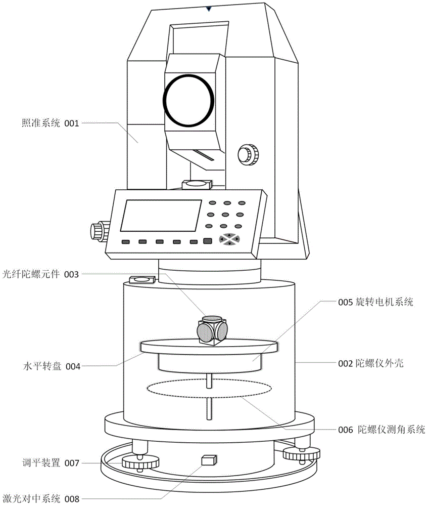
[0104] Place the instrument at one of the stations of a known survey line, and place a reflective prism at the other station; connect the power supply of the gyroscope, turn on the switch of the laser transmitter 24, and move the instrument until the laser beam of the laser transmitter 24 shoots to the station. Logo; adjust the foot screw 22 to center the air bubble in the gyroscope vial 5. The operation of centering and adjusting the foot screw 22 is repeated repeatedly until the instrument is accurately centered and leveled. Insert the gyroscope cable into the power cable interface 19, turn on the external power switch to provide power for the instrument; start the gyroscope, at this time the gyroscope angle measuring system 006 will automatically judge ...


PUM


Abstract

The invention provides a method for determining rotational angular velocity of the earth by utilizing a fiber-optic gyroscope. The method is used for determining the rotational angular velocity of the earth by utilizing a fiber-optic gyroscope with a three-axis orthogonal fiber-optic gyroscope. The method specifically comprises the following steps: installing an instrument, inputting an initial condition, determining the angular velocity value by the three-axis orthogonal fiber-optic gyroscope, and resolving the rotational angular velocity of the earth according to the formula shown in the description, namely, firstly obtaining the rotational angular velocity of the earth Omega Xe measured by the fiber-optic gyroscope X at a station point, and then similarly resolving the corresponding components of rotational angular velocity of the earth Omega Ye and Omega Ze by a fiber-optic gyroscope Y and a fiber-optic gyroscope Z, and finally resolving the vector sum of Omega Xe, Omega Ye and Omega Ze according to the formula is shown in the description, thus obtaining the final rotational angular velocity of the earth Omega e.

Description

technical field [0001] The invention belongs to the fields of astrometry and celestial mechanics, geodynamics, inertial navigation technology, and geodesy, and can be used in the fields of aviation, aerospace, artificial satellite precision orbit determination, deep space exploration, and global plate movement monitoring research. It provides a A method of measuring the angular velocity of the earth's rotation by using a fiber optic gyroscope. Background technique [0002] Due to the influence of different celestial bodies outside the earth and the physical mechanism inside the earth, the rotation process of the earth is unstable, and the rotation state of the earth is usually described by the parameters of the earth's rotation, including the pole shift and the change of day length, where the pole shift is the rotation of the earth Movement of the shaft relative to the crust. After the pole moves, the latitude, longitude and azimuth of the ground station will change accordi...

Claims


Application Information

Patent Timeline
Patent Type & Authority Applications(China)
IPC IPC(8): G01C19/72
CPCG01C19/72
Inventor 杨志强石震马骥
Owner CHANGAN UNIV
Why Eureka
Try Eureka