Casting forming equipment and process for amorphous alloy component

A casting molding and amorphous alloy technology is applied in the field of casting molding equipment and process for amorphous alloy components, and can solve the problem that the amorphous alloy components are easy to form pores or shrinkage holes, the molding efficiency of the amorphous alloy components is reduced, and the amorphous alloy workpieces work. Cycle extension and other problems, to achieve the effect of shortening the working cycle, shortening the molding cycle, and prolonging the supply cycle

Active Publication Date: 2015-06-03
INST OF METAL RESEARCH - CHINESE ACAD OF SCI +1
View PDF12 Cites 23 Cited by
  • Summary
  • Abstract
  • Description
  • Claims
  • Application Information

AI Technical Summary

Problems solved by technology

In casting technology, when all the actions of each molding are completed, to realize the feeding of raw materials, the vacuum of the main chamber must be broken, or a large amount of gas will be wasted, which will lead to the failure of each working cycle of the amorphous alloy workpiece. Lengthening and reduction in productivity
In addition, in order to realize the molding under vacuum conditions, the mold adds a sealing ring, which leads to no vent holes around the mold cavity during the filling process, making it easy to form air holes or shrinkage cavities on the surface of the amorphous alloy component
In addition, in the reported technologies, the vacuum chamber or protective atmosphere chamber needs to be evacuated for a period of time, or filled with gas with a certain pressure, which leads to a decrease in the forming efficiency of amorphous alloy components.

Method used


Image

  • Casting forming equipment and process for amorphous alloy component

Examples


Embodiment Construction

[0039] The present invention will be described in detail below in conjunction with the accompanying drawings, but it should be understood that the protection scope of the present invention is not limited by specific embodiments.

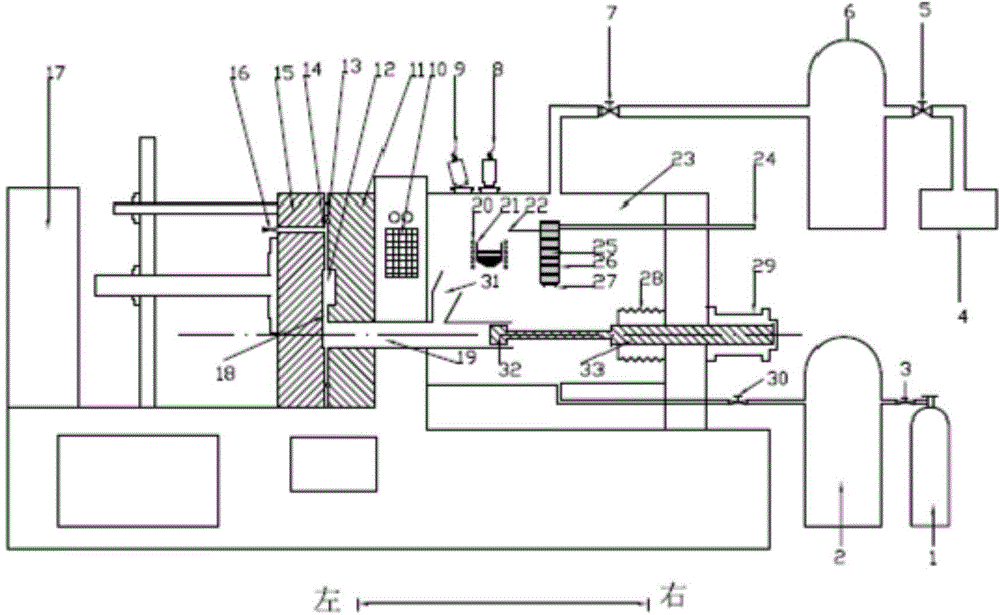
[0040] Such as figure 1 As shown, the casting and molding equipment for amorphous alloy components of the present invention includes an injection system, an alloy melting system, a raw material feeding system, a mold system, a vacuum system and a protective atmosphere system, wherein:

[0041] Alloy smelting system: used for alloy smelting, set in a vacuum chamber 23, including a melting crucible 21 and a heating device 20, the melting crucible 21 is made of aluminum oxide or boron nitride; or, the melting crucible 21 is a belt A graphite crucible with a ceramic coating; the heating device 20 uses induction coils or resistance wires to heat the melting crucible 21; the heating device 20 is arranged outside the melting crucible 21.

[0042] Injection s...


PUM


Abstract

Provided is a device for the casting forming of amorphous alloy components. The device comprises an injection system, an alloy smelting system, a raw material feeding system, a mould system, a vacuum system and a protective atmosphere system, which are used for the preparation of the amorphous alloy components, and can realize the formation by squeezing casting of the amorphous alloy components under a vacuum or a protective atmosphere with a positive pressure. The device is provided with an exhaust port on the mould to effectively solve the problem of forming micro shrinkage cavities on the surface in the process of forming the alloy components so as to improve the quality of the amorphous alloy components. Also provided is a process for the casting forming of the amorphous alloy components. A high vacuum tank or a protective atmosphere tank is used to reach an acquisition time of the vacuum or protective atmosphere with a positive pressure so as to shorten the forming period, save the production cost, and improve the production efficiency.

Description

technical field [0001] The invention relates to the technical field of amorphous alloy forming, in particular to an amorphous alloy component casting forming equipment and process. Background technique [0002] Due to its unique long-range disordered and short-range ordered atomic arrangement structure, bulk amorphous alloys exhibit a series of excellent physical, chemical and mechanical properties, such as high strength, high elasticity, high fracture toughness, high specific strength, Superplasticity, high corrosion resistance, outstanding magnetic properties, excellent formability, etc., are more and more widely used in aviation, aerospace and civil fields. At present, the most successful performance of amorphous alloy application is its outstanding soft magnetic properties, which has made amazing progress and great benefits. Small motors and transformers using amorphous alloys as magnetic components have achieved initial commercial success. The high elasticity of Zr-ba...

Claims


Application Information

Patent Timeline
Patent Type & Authority Applications(China)
IPC IPC(8): B22D17/10B22D17/14B22D17/28B22D17/22
CPCB22D17/10B22D17/14B22D17/002B22D17/145B22D17/203B22D17/263B22D17/28B22D21/02B22D27/003F27D11/02F27D11/06
Inventor 付华萌张海峰王爱民朱正旺张宏伟李宏李扬德李卫荣汤铁装
Owner INST OF METAL RESEARCH - CHINESE ACAD OF SCI
Why Eureka
Try Eureka