Precision laser cutting and micro-hole machining device

A laser cutting and micro-hole processing technology, applied in the field of laser applications, can solve problems such as low production efficiency, complicated processing procedures, and rough hole edges, so as to improve processing efficiency, avoid bottom damage, and improve processing quality.

Active Publication Date: 2015-06-10
HANS LASER TECH IND GRP CO LTD
View PDF4 Cites 10 Cited by
  • Summary
  • Abstract
  • Description
  • Claims
  • Application Information

AI Technical Summary

Problems solved by technology

[0007] The technical problem to be solved by the present invention is to provide a precision laser cutting and microhole processing device for the above-mentioned defects of the prior art, which overcomes the low laser utilization rate and large energy loss when Gaussian laser is used to process microholes in the prior art. , when processing micro-through holes and blind holes, the edge of the hole is not smoot

Method used


Image

  • Precision laser cutting and micro-hole machining device
  • Precision laser cutting and micro-hole machining device
  • Precision laser cutting and micro-hole machining device

Examples


Embodiment 1

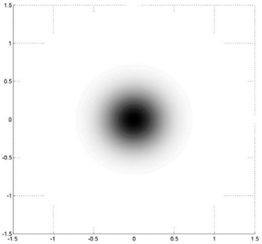
[0030] Such as Figure 5 , 6As shown, the precision laser cutting and microhole processing device of the present embodiment includes a laser 1 for generating Gaussian laser, a beam expander 2 arranged in sequence along the optical path, a rotatable front reflector 3, and a rotatable rear reflector. mirror 4 and focusing lens 5, at least one set of beam shaping system 6 for shaping the Gaussian laser beam into a flat-top laser beam and at least one set of beam shaping system 6 for optimizing the Gaussian laser beam are provided between the front end reflector 3 and the rear end reflector 4 The beam optimization system 7 of the beam, the front reflector 3 is used to selectively reflect the Gaussian laser beam after the beam expander 2 into the beam shaping system 6 or the beam optimization system 7, and the rear reflector 4 is used to convert the Gaussian laser beam from The laser beam emitted by the beam shaping system 6 or the beam optimizing system 7 is reflected into the fo...

Embodiment 2

[0035] Such as Figure 8 As shown, the overall structure of the precision laser cutting and microhole processing device of this embodiment is the same as that of Embodiment 1, the difference is that the precision laser cutting and microhole processing device of this embodiment includes two sets of different beam shaping In system 6, Gaussian laser beams are shaped by two different sets of beam shaping systems 6 to obtain flat-topped laser beams with different spot diameters, so that the processing of micro through holes and blind holes with different diameters can be realized. In order to obtain flat top laser beams with different spot diameters, there are at least the following three methods: one is to use different shaping devices 62, such as diffractive optical shaping devices, shaping devices that use refraction to change the light intensity distribution of beams, non- Select two different shaping devices among the spherical lens shaping device and the lens group shaping d...


PUM


Abstract

The invention relates to the field of laser application, in particular to a precision laser cutting and micro-hole machining device. The precision laser cutting and micro-hole machining device comprises a laser as well as a beam expansion device, a front-end reflective mirror, a rear-end reflective mirror and a focusing lens which are arranged in sequence along a light path, wherein at least one beam shaping system used for shaping Gaussian laser beams into flat-top laser beams and at least one beam optimization system used for optimizing the Gaussian laser beams are arranged between the front-end reflective mirror and the rear-end reflective mirror; the front-end reflective mirror is used for reflecting the Gaussian laser beams passing through the beam expansion device into the beam shaping system or the beam optimization system; the rear-end reflective mirror is used for reflecting laser beams emitted by the beam shaping system or the beam optimization system into the focusing lens. Only by switching the beam shaping system or the beam optimization system for production and machining, switching between micro-hole machining and cutting machining can be realized, so that the operation is simple and the production efficiency is high; with the adoption of the beam shaping system, the micro-hole machining quality can be effectively improved while the laser utilization rate is increased and the laser machining efficiency is improved.

Description

technical field [0001] The invention relates to the field of laser applications, in particular to a precision laser cutting and microhole processing device. Background technique [0002] At present, laser processing, as an advanced manufacturing technology in the processing field, has been widely used in important sectors of the national economy such as automobiles, electronics, electrical appliances, aviation, metallurgy, and machinery manufacturing. play an increasingly important role. [0003] Laser processing technology uses a focused high-power-density laser beam to irradiate the processing material, so that the irradiated material is rapidly melted and vaporized, and at the same time, the molten material is blown away by the high-speed airflow coaxial with the beam, and the motion system drives the processing workpiece or cutting device to move , so as to realize the cutting or punching of the workpiece. [0004] The cutting of the workpiece generally adopts such as ...

Claims


Application Information

Patent Timeline
IPC IPC(8): B23K26/38B23K26/382B23K26/064
CPCB23K26/38
Inventor 赵建涛肖磊杨锦彬宁艳华高云峰
Owner HANS LASER TECH IND GRP CO LTD
Why Eureka
Try Eureka