
Steam heating type rapid heat cycle molding injection mold

A heating technology for injection molds, applied in the field of steam-heated high-gloss injection molds, can solve the problems of reducing mold heat capacity, low heat cycle efficiency, and high mold cost, and achieve good economic benefits, high heat cycle efficiency, and low production costs Effect

Inactive Publication Date: 2015-06-10
SHENZHEN INSTITUTE OF INFORMATION TECHNOLOGY
View PDF6 Cites 4 Cited by
  • Summary
  • Abstract
  • Description
  • Claims
  • Application Information

AI Technical Summary

Problems solved by technology

According to the above requirements for high-gloss injection mold cavity plate materials, people often choose imported high-quality mold steels, such as CENAI from Hitachi, NAK80 from Daido, and VIDAR SUPERIOR from Sweden. These mold materials have good dimensional stability. It is the first choice for high-gloss injection mold materials due to its high performance, high polishing performance and high thermal shock and thermal fatigue resistance. However, these high-quality steel materials are expensive, resulting in high mold costs.
[0004] The existing steam-heated high-gloss injection mold still has the outstanding problem of low thermal cycle efficiency. In order to shorten the molding cycle and improve injection production efficiency, the structural design of the steam-heated high-gloss injection mold must fully consider the requirements of rapid heating and rapid cooling of the mold. This requires that a special design method or structure must be adopted in the mold design to minimize the heat capacity of the mold, thereby improving the thermal cycle efficiency

Method used


Image

  • Steam heating type rapid heat cycle molding injection mold
  • Steam heating type rapid heat cycle molding injection mold

Examples


Embodiment Construction

[0036] In order to better understand the technical solution of the present invention, the present invention will be further described below in conjunction with the accompanying drawings and specific embodiments.

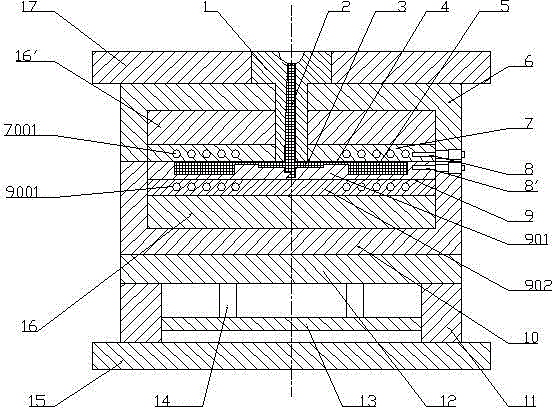
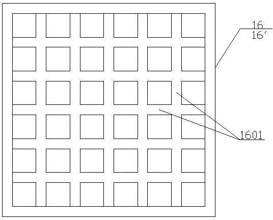
[0037] Such as figure 1 As shown, a steam-heated high-gloss injection mold disclosed by the present invention includes a core plate 7 and a cavity plate 9, and the cavity plate and the core plate are respectively connected with supporting plates 16 and 16 ′. The support plates 16 and 16' adopt a plurality of ordinary steel plates 1601 with poor thermal conductivity, and are connected into a grid-like structure through criss-cross connections. The grid-like structure is composed of regular polygonal meshes, and the shape, size and distribution of the meshes are It is necessary to optimize the design to ensure the performance requirements of all aspects of the mold. The cavity plate 9 is composed of a molding layer 901 and a matrix layer 902, and the thickness of the ...


PUM

PropertyMeasurementUnit
thicknessaaaaaaaaaa

Abstract

The invention relates to a steam heating type rapid heat cycle molding injection mold. The mold comprises a core plate and a cavity plate, wherein the core plate and the cavity plate are respectively connected with support plates; the support plates adopts ordinary steel plates with poor heat-conducting properties; the ordinary steel plates are connected to form a latticed structure in a criss-cross manner; the cavity plate is formed by a molding layer and a base layer; the base layer is prepared with ordinary hot work mold steel by adopting a conventional process; the molding layer is prepared by superposing high-quality mold steel with good heat fatigue resistance and wear resistance and terrific polishing property on the surface of the base layer by adopting an overlay welding method; heating and cooling pipelines are arranged on the core plate and the base layer of the cavity plate and are connected with temperature control devices to achieve rapid heating and cooling of the molding surface of the mold. The steam heating type rapid heat cycle molding injection mold has the beneficial effects that innovative designs of the material, the structure, and the like are put forward, so that the mold has the obvious advantages of low production cost, high heating and cooling efficiency, good product surface quality, light mold weight, and the like.

Description

technical field [0001] The invention belongs to the technical field of injection molding in the subject of material processing, and in particular relates to a steam-heated high-gloss injection mold. Background technique [0002] As a green molding technology with great development potential, high-gloss injection molding technology has attracted a large number of scholars to research and promote it. However, the development of high-gloss injection molding technology is still immature, and there are still many problems to be solved. Especially in high-gloss injection mold design and manufacturing technology, the existing problems are particularly prominent. [0003] Since the molding surface of the high-gloss injection mold requires extremely high polishing precision, firstly, the mold material must have excellent polishing performance; secondly, due to the repeated alternating of rapid heating and rapid cooling in the normal production process, the molded parts of the high-gl...

Claims


Application Information

Patent Timeline
Patent Type & Authority Applications(China)
IPC IPC(8): B29C45/73B29C33/38
Inventor 刘秀娟李东伟姜俊侠
Owner SHENZHEN INSTITUTE OF INFORMATION TECHNOLOGY
Learn More