A heat transfer roller with graphite interlayer and heat transfer method thereof

A graphite layer and graphite technology, which is applied to the heat transfer roller and its heating field, can solve the problems of reduced heat transfer efficiency and temperature response speed, increased material, and reduced roller space, so as to reduce production and operation costs and improve The effect of improving temperature and temperature uniformity can be used

Active Publication Date: 2017-12-29
史春彦 +1
View PDF3 Cites 0 Cited by
  • Summary
  • Abstract
  • Description
  • Claims
  • Application Information

AI Technical Summary

Problems solved by technology

Its disadvantages are: there are many temperature control sections in the segmented method, large investment, complicated installation of heating elements (especially for the inside of the roller with small space), and the temperature in the connecting area of ​​adjacent sections is not easy to control
If a failure occurs in one of the multi-sections, it is not appropriate to find out in time, resulting in product quality problems
It is also a common method to increase the thickness of the heat transfer layer (for example, the temperature of pancakes is relatively uniform with a thick pan), and its disadvantages are: the weight and cost of the device are increased, and the installation space of the heating device in the roller is reduced. The thick metal surface also greatly reduces the heat transfer efficiency and temperature response speed
The use of heat pipe technology is a technology with better heat transfer uniformity. Its disadvantages are: high cost, small application range of temperature heating (limited by the characteristics of the medium in the heat pipe, related to the gas-liquid conversion temperature of the medium), and certain risks ( When the gas-liquid transition temperature is too high, the pressure caused by vaporization will easily lead to explosion)
Disadvantages: A rotary joint is required, and the rotary seal of the rotary joint depends on the graphite ring, which will inevitably cause wear and leakage, and the dripping of the oil and heat medium will form oil pollution and affect the surrounding sanitation environment
Disadvantages: ①The temperature range corresponding to one liquid is not wide enough, which limits the operating temperature range of the equipment
②At high temperature, the pressure inside the heat pipe is high, there are unsafe factors, and there is a possibility of explosion when the temperature control is out of control
③ High sealing requirements, easy to leak at high temperature and high pressure, and the reduction of volatile liquid will cause the heat pipe to fail
Disadvantages: multi-stage temperature control complicates the temperature measurement and temperature control structure of the roller
The uniform temperature effect is compensated by increasing the thickness of the roller, which increases the material used for the roller, increases the weight, reduces the heat transfer efficiency, and reduces the inner space of the roller.
It is difficult to manufacture small-diameter rollers due to insufficient space and volume
Due to environmental protection requirements and cost issues, many rollers heated by steam, hot water, and hot oil are turning to electric direct heating, but the main problem is that the temperature uniformity is not enough, and the temperature accuracy is ±5°C, such as application number 201210135722.9 patent
In the prior art, there is an interlayer oil injection method to reduce temperature unevenness, without pump circulation. The disadvantage is that the temperature difference is large, and there is a risk of oil thermal expansion and explosion. For details, refer to the Chinese patent application number 201020522359.2

Method used


Image

  • A heat transfer roller with graphite interlayer and heat transfer method thereof
  • A heat transfer roller with graphite interlayer and heat transfer method thereof
  • A heat transfer roller with graphite interlayer and heat transfer method thereof

Examples


Embodiment Construction

[0040] The present invention will be described in detail below in conjunction with the accompanying drawings.

[0041] Heat transfer roller and graphite interlayer

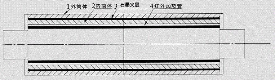
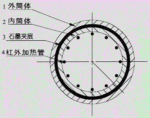
[0042] figure 1 with figure 2 An exemplary heat transfer roller with a graphite interlayer is shown in the present invention, and the heat transfer roller includes: an outer cylinder body 1 , an inner cylinder body 2 , a graphite interlayer layer 3 , and an infrared heating tube 4 . The graphite interlayer 3 is sandwiched between the inner cylinder 2 and the outer cylinder 1 of the heat transfer roller. Both the inner cylinder body 2 and the outer cylinder body 1 are metal layers.

[0043] The material of the graphite interlayer can be selected from various forms of graphite materials with high surface thermal conductivity, preferably graphite flakes. The graphite interlayer can accelerate the temperature diffusion speed in the plane direction, and the uneven temperature distribution obtained from the uneven ...


PUM


Abstract

The invention discloses a heat transfer roller with a graphite interlayer and a heat transfer method thereof. The heat transfer roller includes: an outer cylinder 1 , an inner cylinder 2 , a graphite interlayer 3 , and an infrared heating tube 4 . The graphite interlayer 3 is sandwiched between the inner cylinder 2 and the outer cylinder 1 of the heat transfer roller. Both the inner cylinder body 2 and the outer cylinder body 1 are metal layers. The invention utilizes the very high thermal conductivity of the graphite plane to improve the temperature transfer efficiency along the heat transfer roller surface, and an intermediate layer of graphite material is arranged in the heat transfer roller device to greatly improve the temperature uniformity of the heat transfer roller.

Description

technical field [0001] The invention relates to a heat transfer roller with a graphite interlayer and a heating method thereof. Background technique [0002] The existing technologies for controlling the temperature uniformity of the heat transfer roller mainly include multi-point and small-area heat source temperature control, increasing the thickness of the homogeneous heat transfer material, and using heat pipes for heat transfer. The multi-point small-area heat source temperature control technology is to divide the heat source into different sections (or areas), and control the temperature of a certain section through independent setting to achieve the control of the overall temperature consistency. Its disadvantages are: there are many temperature control sections in the segmented method, large investment, complicated installation of heating elements (especially for the inside of the roller with small space), and the temperature in the connecting area of ​​adjacent sect...

Claims


Application Information

Patent Timeline
Patent Type & Authority Patents(China)
IPC IPC(8): B32B1/08B32B9/04B32B15/00B32B38/00
Inventor 史春彦刘强
Owner 史春彦
Why Eureka
Try Eureka