Disk brake cylinder assembly with parking mechanism and brake caliper

A disc brake and parking mechanism technology, applied in the direction of brake actuators, gear transmission mechanisms, mechanical equipment, etc., can solve the wear and tear of parts and the reduction of mechanism efficiency, increase the difficulty of parts manufacturing and coordination, processing accuracy and assembly requirements Advanced problems, to achieve the effect of reducing manufacturing costs, reducing the number of parts, and improving matching accuracy

Inactive Publication Date: 2015-06-17
武汉万向汽车制动器有限公司
View PDF7 Cites 7 Cited by
  • Summary
  • Abstract
  • Description
  • Claims
  • Application Information

AI Technical Summary

Problems solved by technology

[0007] 1. Using the anti-rotation stop screw, the transmission of parking force will be affected by the bias force of the stop screw, which will aggravate the wear of the parts and reduce the efficiency of the mechanism; and the stop screw may also loosen and cause damage under the action of force. Leakage or parking failure;
[0008] 2. The eccentric anti-rotation pin is adopted, and the machining accuracy and assembly requirements of its parts are high; the set eccentric anti-rotation pin is under the action of bias force, resulting in poor centering of the force transmission parts and low force transmission efficiency
[0009] 3. Although the use of the fixed sleeve solves the influence caused by the bias force, it increases the number of parts and the difficulty of manufacturing fit. The fit accuracy of each part directly affects the centering performance of the parts and reduces the efficiency of the manipulator;
[0010] 4. In the above-mentioned known parking brake mechanism, the brake mechanism is affected by the reaction force of the stop screw and the eccentric anti-rotation pin or the gap formed by the multiple mating surfaces of the fixed sleeve and the manufacturing error, which will cause the force transmission parts to Poor centering, the force transmitted to the piston will deviate from the axis of the piston, and the parts will be unbalanced in force; therefore, in the above-mentioned known parking mechanism, an auxiliary piston is added in order to overcome the defects of the prior art, and its purpose is to Increase the centering of the screw sleeve or screw; but the addition of auxiliary pistons requires additional sealing rings and additional vent holes on the pistons, which increases the risk of oil leakage

Method used


Image

  • Disk brake cylinder assembly with parking mechanism and brake caliper
  • Disk brake cylinder assembly with parking mechanism and brake caliper
  • Disk brake cylinder assembly with parking mechanism and brake caliper

Examples


Embodiment 1

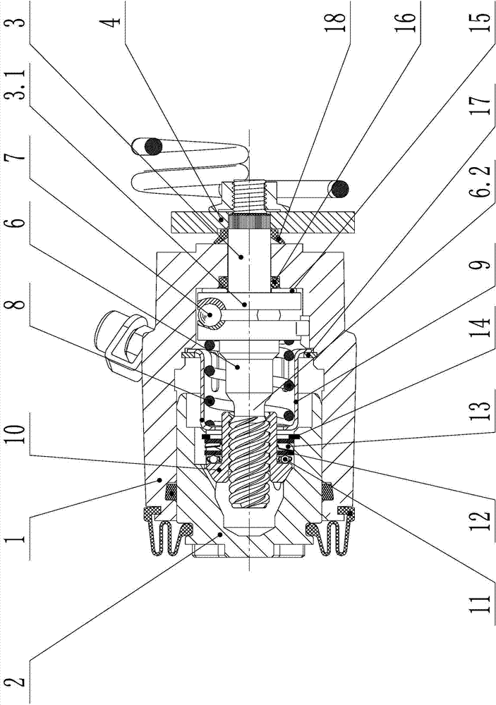
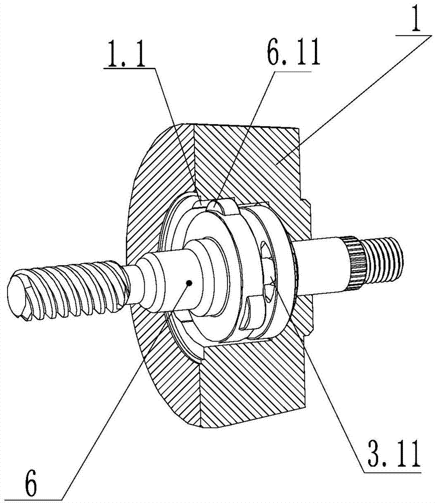
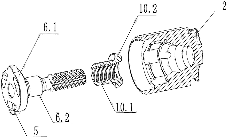
[0042]As shown in the figure: the disc brake cylinder assembly with parking mechanism includes a hollow housing 1 with openings that gradually become smaller from left to right. Piston 2, stroke adjustment screw 6 and The drive shaft 3; the drive shaft 3 passes through the bottom end of the cylinder hole at the other end of the housing 1 and is connected with the rod arm assembly 4 outside the housing through a straight-tooth spline; the shaft wall between the drive shaft 3 and the rod arm assembly 4 is set Leather cup 18; drive shaft 3 is provided with disc 3.1 at one end in the cylinder body, and the outer surface of disc 3.1 is distributed with a plurality of first slope-shaped fairways 3.11 at the center, and stroke adjustment screw rod 6 is made up of screw rod 6.2 and ball disc 6.1 The overall structure; the ball disc 6.1 of the stroke adjustment screw 6 is provided with a second slope-shaped ballway 5 corresponding to the first slope-shaped ballway 3.11 of the drive shaf...

Embodiment 2

[0053] In this embodiment, the integral parking brake caliper assembly structure including the brake cylinder assembly includes all the structures of the disc brake cylinder assembly in Embodiment 1, and its housing 1 is an integral structure. The body is extended with a claw 19 opposite to the end face of the piston 2, and a friction plate 20 is placed between the piston 2 and the claw 19 to form a clamping space for the brake disc 22. The structure also includes a bracket 21 connecting the housing and the fixed friction plate 20 .

[0054] Its working process is identical with embodiment 1.

Embodiment 3

[0056] This embodiment includes the overlapping combined parking brake caliper assembly structure of the brake cylinder assembly, which includes all the structures of the disc brake cylinder assembly in Embodiment 1, and also includes: bridge plate 23, connection Screw 24 and friction plate 20.

[0057] Its working process is identical with embodiment 1.


PUM


Abstract

The invention discloses a disk brake cylinder assembly with a parking mechanism and a brake caliper. The disk brake cylinder assembly comprises a cylinder block, a piston, a travel adjusting threaded sleeve, a travel adjusting threaded rod, a steel ball, a drive shaft, a plane sliding bearing, an O-shaped seal ring and a spring resetting device. One end of the travel adjusting threaded rod is provided with a multi-head saw-tooth thread. The other end of the travel adjusting threaded rod is a ball disk with slope rolling ways. Arc-shaped guide bosses are evenly distributed on the outer edge of the ball disk, and the bosses are matched with grooves in a cylinder hole and prevent the travel adjusting threaded rod from rotating. The travel adjusting threaded rod has good centering performance, and therefore an auxiliary piston having the centering function in the piston is omitted. By the adoption of the disk brake cylinder assembly with the parking mechanism, the movement type of parts of the parking mechanism is simplified, and the risk that multiple leaking points exist in existing known structures is avoided. The disk brake cylinder assembly with the parking mechanism is simple in structure and higher in safety performance, the parts can be more easily machined, the transmission efficiency of the parking brake force is improved, and low cost, high performance and higher safety performance are effectively combined.

Description

technical field [0001] The invention belongs to the field of a disc brake mechanism with a parking mechanism, and specifically refers to a disc brake cylinder assembly with a parking brake mechanism. The invention also relates to a rear- Parking disc brake calipers. Background technique [0002] In the currently known disc brake calipers with parking brake mechanisms, the stroke adjustment screw and the adjustment screw sleeve are generally used to transmit the axial control force, and the friction material of the brake pad is compensated by the thread extension. wear and tear. During the transmission of the axial braking force, the force acts on the helical surface of the matching screw and the screw sleeve, which will cause the screw or the screw sleeve to rotate and relax the force. In order to ensure that there is no slack in the process of force transmission, an anti-rotation mechanism must be added to prevent the screw or screw sleeve from rotating, and only allow ax...

Claims


Application Information

Patent Timeline
Patent Type & Authority Applications(China)
IPC IPC(8): F16D65/14F16D121/02
Inventor 汪文高毛燕明程家兵李双莉魏钦琪谢芬
Owner 武汉万向汽车制动器有限公司
Why Eureka
Try Eureka