High-pressure-resistant flat heat pipe and machining method thereof

A technology of flat heat pipe and high pressure resistance, which is applied in the direction of indirect heat exchangers, lighting and heating equipment, etc., can solve the problems of limiting the use temperature range of flat heat pipes and the pressure resistance of flat heat pipes, so as to broaden the use temperature range and meet the requirements of reflection. Gravity performance, effect of enhancing pressure resistance performance

Active Publication Date: 2015-06-17
SHANGHAI INST OF SATELLITE EQUIP
5 Cites 13 Cited by

AI-Extracted Technical Summary

Problems solved by technology

However, flat heat pipes using working fluids such as water and alcohol are constrained by the boiling point and condensation point of the working fluid, which severely limits the operating temperature range of flat heat pipes.
If ammonia is used as the working fluid, the operating temperature range of the flat heat pipe can...

Abstract

The invention provides a high-pressure-resistant flat heat pipe and a machining method thereof. The high-pressure-resistant flat heat pipe comprises an upper cover plate, a lower cover plate, capillary cavities and reinforcing ribs, wherein the upper cover plate is connected with the lower cover plate to form an airtight cavity, the reinforcing ribs arranged into a dot matrix are arranged on the upper cover plate and located in the airtight cavity, the upper cover plate is connected with the lower cover plate through the reinforcing ribs, communicated steam channels are arranged outside the reinforcing ribs, the capillary cavities are formed in the outer surfaces of the reinforcing ribs, and each capillary cavity is provided with a plurality of capillary core structures used for adsorbing liquid-phase working media. By arranging the cubic reinforcing ribs on the upper cover plate evenly, the pressure resistance of the flat heat pipe is improved. The inner surface is filled with the capillary cavities provided with the capillary core structures through sintering, and thus antigravity performance is realized.

Application Domain

Technology Topic

Image

  • High-pressure-resistant flat heat pipe and machining method thereof
  • High-pressure-resistant flat heat pipe and machining method thereof
  • High-pressure-resistant flat heat pipe and machining method thereof

Examples

  • Experimental program(1)

Example Embodiment

[0038] The present invention will be described in detail below in conjunction with specific embodiments. The following examples will help those skilled in the art to further understand the present invention, but do not limit the present invention in any form. It should be pointed out that for those of ordinary skill in the art, a number of modifications and improvements can be made without departing from the concept of the present invention. These all belong to the protection scope of the present invention.
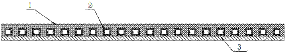
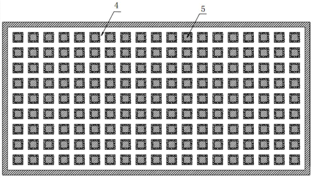
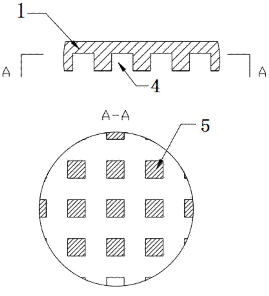
[0039] In this embodiment, the high-pressure-resistant flat heat pipe provided by the present invention includes an upper cover plate 1, a lower cover plate 3, a capillary cavity 2 and a reinforcing rib 5;
[0040] Wherein, the upper cover plate 1 is connected to the lower cover plate 3 to form a closed cavity; the upper cover plate 1 is provided with stiffeners 5 arranged in a lattice pattern; the stiffeners 5 are evenly arranged on the upper On the inner surface of the cover plate 1. The reinforcing ribs 5 are arranged in the sealed cavity and the upper cover plate 1 is connected to the lower cover plate 3 through the reinforcing ribs 5; the outside of the reinforcing ribs 5 is provided with a communicating steam channel 4; The outer surface of the reinforcing rib 5 is provided with the capillary cavity 2. The upper cover plate 1 and the lower cover plate 3 and between the lower cover plate 3 and the reinforcing ribs 5 are hermetically connected by diffusion welding. The inner surface of the lower cover 3 is provided with a capillary cavity 2. The capillary cavity 2 is made by sintering metal powder.
[0041] For saturated ammonia steam, the pressure is dozens of times higher than that of working fluids such as water and acetone, and a pressure-resistant structure must be designed. By evenly arranging reinforcing ribs on the upper cover plate, the structural strength of the present invention is enhanced, and the problem of poor high performance resistance of the present invention is solved.
[0042] The capillary cavity 2 is provided with a plurality of capillary wick structures, which are used to adsorb the liquid phase working fluid and suck the liquid ammonia at the bottom to the upper heat source through the capillary force of the capillary wick to solve the reflux and resistance of liquid ammonia. Gravity issues.
[0043] The steam channels 4 extend along the length or width direction of the upper cover plate 1; a plurality of steam channels 4 extending along the length direction of the upper cover plate 1 are parallel to each other; and a plurality of steam channels 4 extend along the width direction of the upper cover plate 1. The steam channels 4 extending in the direction are parallel to each other; the steam channels 4 extending in the length direction of the upper cover plate 1 are perpendicular to the steam channels 4 extending in the width direction of the upper cover plate 1.
[0044] The method for processing a high-pressure-resistant flat heat pipe provided by the present invention includes the following steps:
[0045] Step 1: On the upper cover plate 1 by cross-milling the surface of the aluminum plate, cross-cut rectangular grooves to form the reinforcing rib 5;
[0046] Step 2: Filling and sintering the metal powder in the intersecting rectangular channels to form a capillary cavity 2 with a capillary core structure;
[0047] Step 3: Mill the cross steam channel 4 in the capillary cavity 2 of the cross rectangular channel;
[0048] Step 4: Fill the inner surface of the lower cover plate 3 with metal powder and sinter it to form a capillary cavity 2 with a capillary core structure, and then mill out the welding interface of the reinforcing rib 5 from the capillary cavity 2.
[0049] The upper cover 1 is processed by cross-milling the surface of the aluminum plate to form a rectangular channel to form a reinforcing rib; by filling the cross rectangular channel with metal powder and sintering to form a capillary core structure; passing through the internal capillary core structure of the cross rectangular channel The cross steam channel 4 is machined to reduce the complexity of sintering. The lower cover plate 3 is filled with metal powder on the surface of the aluminum plate and sintered to form a capillary core structure, and then the welding interface of the reinforcing rib 5 is milled from the capillary core structure.
[0050] Compared with the structure with poor pressure resistance of ordinary flat heat pipes, the high pressure flat heat pipe provided by the present invention can effectively solve the problems of pressure resistance and gravity resistance of existing flat heat pipes, and broaden the use temperature of flat heat pipes Range (-50℃~100℃), at the same time, realize the purpose of rapid heat expansion and heat dissipation of the point heat source.
[0051] When the high-pressure-resistant flat heat pipe provided by the present invention is used, the closed cavity is evacuated and filled with ammonia working fluid. A heat source with high heat flux is placed on the surface of the upper cover plate 1 and the lower cover plate 3. When the heat is transferred from the heat source to the evaporation zone, the ammonia working fluid in the capillary cavity 2 is heated to produce the phenomenon of liquid phase gasification. The working fluid absorbs heat and rapidly expands in volume. The ammonia working fluid in the gas phase quickly diffuses in the cross steam passage 4 of the entire closed cavity; when the gas phase ammonia working fluid contacts the condensation zone, it will condense and release The accumulated heat energy during evaporation, the condensed liquid phase working fluid will return to the evaporation heat source due to the capillary adsorption of the capillary wick structure. This process will be repeated in the cavity, so that the cycle can take away the heat generated by the heat source.
[0052] The specific embodiments of the present invention have been described above. It should be understood that the present invention is not limited to the above specific embodiments, and those skilled in the art can make various deformations or modifications within the scope of the claims, which does not affect the essence of the present invention.

PUM

no PUM

Description & Claims & Application Information

We can also present the details of the Description, Claims and Application information to help users get a comprehensive understanding of the technical details of the patent, such as background art, summary of invention, brief description of drawings, description of embodiments, and other original content. On the other hand, users can also determine the specific scope of protection of the technology through the list of claims; as well as understand the changes in the life cycle of the technology with the presentation of the patent timeline. Login to view more.

Similar technology patents

LDMOS and manufacturing method thereof

Owner:SHENZHEN NANSHUO MINGTAI TECH CO LTD

Classification and recommendation of technical efficacy words

  • Wide operating temperature range
  • Improve pressure resistance

Ticket and card reclaiming device

Owner:SHENYANG SIASUN ROBOT & AUTOMATION

C-band heavy-power circulator

Owner:CHENGDU TIGER MICROWAVE TECH

Coriolis mass flowmeter

InactiveUS6895826B1Improve pressure resistancePrevent inertial momentDirect mass flowmetersEngineeringVibration sensor
Owner:OVAL CORP

Vacuum switch tube

Owner:BEIJING BOE VACUUM ELECTRONICS CO LTD
Why Eureka
Try Eureka