A high-sensitivity micro-vibration detection method

A detection method and high-sensitivity technology, applied in measurement devices, measurement of ultrasonic/sonic/infrasonic waves, instruments, etc., can solve the problems of difficult detection of small electrical signals and low sensitivity of micro-detection, avoid detection difficulties, and facilitate system integration. , the effect of simple structure

Active Publication Date: 2017-12-05
NORTHWESTERN POLYTECHNICAL UNIV
View PDF5 Cites 0 Cited by
  • Summary
  • Abstract
  • Description
  • Claims
  • Application Information

AI Technical Summary

Problems solved by technology

[0005] The purpose of the present invention is: in order to overcome the shortcomings of the existing micro-detection sensitivity and the difficulty of detecting small electrical signals, a detection method for micro-vibration based on light diffraction of a high-aspect-ratio column array is proposed. By detecting the change of the diffraction spot Realize the detection of tiny vibrations, this method has the advantages of simple process and high sensitivity

Method used


Image

  • A high-sensitivity micro-vibration detection method
  • A high-sensitivity micro-vibration detection method
  • A high-sensitivity micro-vibration detection method

Examples


Embodiment 1

[0021] In this embodiment, a high aspect ratio nano-column array composed of 5 rows and 5 columns is provided to realize the light diffraction detection method for low-frequency sound detection, which specifically includes the following steps:

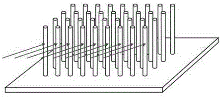
[0022] Step 1: On the silicon substrate, use photoresist as a mask to etch silicon with high-density plasma etching technology to form high-aspect-ratio nanopillars with a period of 2 microns, a diameter d of 500 nanometers, and a height h of 200 microns array.

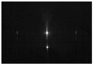
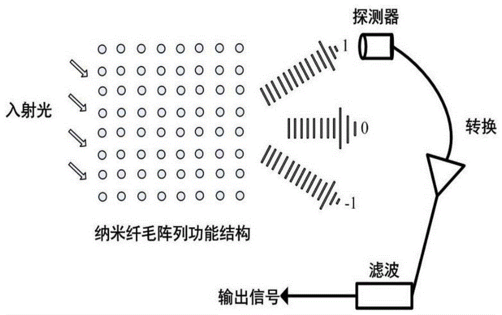
[0023] Step 2: Select a red laser with a wavelength of 520 nm, and control the beam diameter to about 50 μm through various components such as an aperture. The laser beam is incident on one side of the high-aspect-ratio nanoarray at an angle of 45°, forming light and dark diffraction fringes on the other side.

[0024] Step 3: When no external sound pressure change is felt, the diffraction fringes of the high aspect ratio nano-column array vibrate regularly. When the externa...

Embodiment 2

[0028] In this embodiment, a light diffraction detection method for realizing acceleration by a high-aspect-ratio nano-column array composed of 3 rows and 3 columns is given, which specifically includes the following steps:

[0029] Step 1: On the silicon substrate, use photoresist as a mask to etch silicon with high-density plasma etching technology to form high aspect ratio nanopillars with a period of 1 micron, a diameter d of 300 nanometers, and a height h of 200 microns array.

[0030] Step 2: Select a red laser with a wavelength of 520 nm, and control the beam diameter to about 50 μm through various components such as an aperture. The laser beam is incident on one side of the high-aspect-ratio nanoarray at an angle of 45°, forming light and dark diffraction fringes on the other side.

[0031] Step 3: The device is moved with an acceleration of a, and the high aspect ratio nano-array is shifted under the action of the acceleration, causing the diffraction fringes to chan...


PUM


Abstract

The invention discloses a method for detecting microvibration based on a high aspect ratio nanometer array, which belongs to the field of microvibration detection. The method is: after the beam is shaped, the laser is incident on the high-aspect-ratio nano-array from the side, forming light and dark diffraction fringes on the other side; when the high-aspect-ratio column array feels external vibrations, it will vibrate synchronously, resulting in Diffraction fringes change accordingly; read the trajectory of the diffraction fringe ±1 order, and obtain the change angle θ of the diffraction fringe. According to the relevant knowledge of theoretical mechanics and material mechanics, the relationship between the external load p and the angle θ is deduced, so that The purpose of measuring the external micro-vibration load is achieved by detecting the change angle θ of the diffraction fringes. The invention has simple structure and is easy to realize system integration. At the same time, compared with the existing detection methods, it avoids the detection difficulty of tiny electrical signals and improves the accuracy of the detection system.

Description

[0001] Field [0002] The invention relates to a method for detecting micro-vibrations based on high aspect ratio nano-arrays, which is mainly used for precise measurement of micro-acoustic vibrations and belongs to the field of micro-vibration detection. Background technique [0003] With the increasingly prominent position of marine economy and military strategy, the acoustic signals of various military targets are becoming more and more complex, and there is an urgent need to study new methods for detecting, locating and tracking targets. Sound waves are the best medium for long-distance transmission in water. However, with the development of acoustic countermeasures and anti-resistance, especially after most submarines adopt anechoic tiles, the operating frequency of sonar is required to drop below about 3kHz, which puts forward more requirements for hydrophone detection. It is a big challenge; when the low-altitude or ground moving target is located in the radar blind zon...

Claims


Application Information

Patent Timeline
Patent Type & Authority Patents(China)
IPC IPC(8): G01H11/02
Inventor 马志波苑伟政姜澄宇乔大勇孟海莎
Owner NORTHWESTERN POLYTECHNICAL UNIV
Why Eureka
Try Eureka