Linear variable-area wave zone plate with feature of long focal length

A zone plate and variable area technology, applied in the field of long focal depth optical components, can solve problems such as inapplicability, and achieve the effect of easy processing and high lateral resolution

Active Publication Date: 2015-07-08
LASER FUSION RES CENT CHINA ACAD OF ENG PHYSICS
View PDF5 Cites 8 Cited by
  • Summary
  • Abstract
  • Description
  • Claims
  • Application Information

AI Technical Summary

Problems solved by technology

However, the vast majority of optical elements designed by the above-mentioned theoretical method are phase-type, generally use quartz as the material, and are only applicable to the visible light band, not suitable for vacuum ultraviolet and soft X-ray bands

Method used


Image

  • Linear variable-area wave zone plate with feature of long focal length
  • Linear variable-area wave zone plate with feature of long focal length
  • Linear variable-area wave zone plate with feature of long focal length

Examples


Embodiment 1

[0038] This embodiment discloses a linear variable area zone plate with long focal depth suitable for the visible light band, and gives the design method of the zone plate layout, the working mode and diffraction characteristics of the zone plate, and the preparation method of the zone plate .

[0039] 1. Design method of zone plate layout

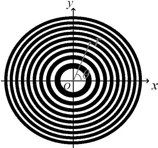
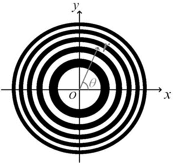
[0040] Zone plate in ( )with The structure under the coordinate system is as follows Figure 1a with Figure 1b As shown, the variables in the two coordinate systems satisfy the conversion relationship: . in Under the coordinate system, the structure of the linear variable area zone plate of the present invention is as Figure 1b As shown, it is a quasi-period structure, and each period corresponds to a ring zone of the zone plate, the period And zone area Satisfaction relationship: . There is a linear change between adjacent cycles And satisfied , That is, the area between the corresponding adjacent loops changes linearl...

Embodiment 2

[0056] Preparation of X-ray lithography replication zone plate

[0057] a: Same as step c in the preparation method of Example 1;

[0058] b: Use the mask produced in embodiment 1 as the original exposure image, and perform X-ray exposure on the film produced in step a of this embodiment;

[0059] c: Same as step e of the preparation method in Example 1;

[0060] d: The photoresist is removed to obtain a replication zone plate of a linear variable area zone plate with long focal depth characteristics.

Embodiment 3

[0062] Preparation of anti-wave zone plates

[0063] a: By means of transfer, using the same silicon wafer, gold film and photoresist materials as in Example 1 or Example 2, a light-transmitting substrate is added under the gold film as a support. The reverse pattern structure of the second embodiment can be used to make the anti-wave zone plate of the linear variable area zone plate with long focal depth. The diffraction pattern of the anti-wave zone plate is the same as that of the first or second embodiment.


PUM


Abstract

The invention provides a linear variable-area wave zone plate with the feature of a long focal length. The wave zone plate is formed by arranging a series of light-blocking half-wave zones and a series of light-transmitting half-wave zones alternately, wherein each light-blocking half-wave zone and the corresponding light-transmitting half-wave zone adjacent to the light-blocking half-wave zone form a wave zone; in each wave zone, the area of the light-blocking half-wave zone and the area of the light-transmitting half-wave zone are equal; between every two adjacent wave zones, the areas change linearly; the focal length delta f is approximately determined by the formula of delta f = N*delta S / 2*pi*lambda, N is the number of wave band rings, the delta S is the change quantity of the areas of every two adjacent wave zones, and lambda is the length of an incidence light wave. The linear variable-area wave zone plate is suitable for the fields of laser cutting, precise machining and optical imaging.

Description

technical field [0001] The invention relates to the field of optical elements with long focal depth, in particular to a long focal depth stretching device which is formed by a series of light-blocking half-wave bands and light-transmitting half-wave bands alternately arranged by linearly changing the area of ​​adjacent wave bands. Depth-of-focus zone plate. Background technique [0002] Optical components with long depth of focus and high lateral resolution have important applications in many fields, such as laser lithography, laser cutting, laser scanning, precision machining, and optical imaging in harsh environments. However, for traditional lenses, there is a mutually restrictive relationship between long focal depth and high lateral resolution, that is, high lateral resolution requires larger NA (numerical apertures), while long focal depth requires small NA. Therefore, it is a very important technical problem to seek a focusing technology that satisfies the requiremen...

Claims


Application Information

Patent Timeline
Patent Type & Authority Applications(China)
IPC IPC(8): G02B5/18
CPCG02B5/1876
Inventor 曹磊峰范全平刘钰薇杨祖华魏来张强强陈勇钱凤晏卓阳
Owner LASER FUSION RES CENT CHINA ACAD OF ENG PHYSICS
Why Eureka
Try Eureka