
Austenitic stainless steel welding technology

A technology of austenitic stainless steel and welding technology, applied in welding equipment, welding/welding/cutting items, manufacturing tools, etc., can solve the problems of large argon consumption, rising welding costs, restrictions, etc., and achieve obvious economic benefits and welding The effect of cost reduction and wide source

Inactive Publication Date: 2015-07-22
ZHEJIANG BOFAN POWER EQUIP CORP
View PDF6 Cites 9 Cited by
  • Summary
  • Abstract
  • Description
  • Claims
  • Application Information

AI Technical Summary

Problems solved by technology

[0004] However, in practical applications, when welding large or extra-large stainless steel parts, it is necessary to consume a large amount of argon for protection
Due to the complex preparation process and high cost of argon, the cost of welding increases and the application is limited

Method used


Image

  • Austenitic stainless steel welding technology
  • Austenitic stainless steel welding technology
  • Austenitic stainless steel welding technology

Examples


Embodiment 1

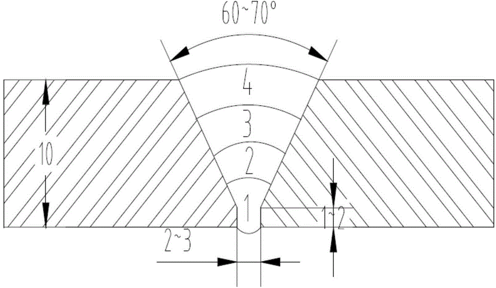
[0018] Refer to attached figure 1

[0019] The stainless steel sheet material is 06Cr19Ni10, the thickness is 10mm, the welding wire type is ER308L, and the V-shaped groove is adopted. The following steps and process parameters are used to make:

[0020] 1) Process a bevel at the stainless steel joint by machining, and use acetone to remove oil and harmful impurities within 20 mm of the surface of the bevel and the base material on both sides of the bevel, and make the welded part and the surrounding area reveal metallic luster. Dry the bevel and surrounding area without residual moisture.

[0021] 2) Selection of weld bevel shape: V-shaped bevel with groove angle of 60°, blunt edge thickness of 2mm, and eliminate burrs.

[0022] 3) The gap between base metal groups is 2mm, and the misalignment of the inner surface of the base metal is less than 2mm.

[0023] 4) The back of the weld adopts airtight measures, only the air inlet and outlet are opened, the back of the weld us...

Embodiment 2

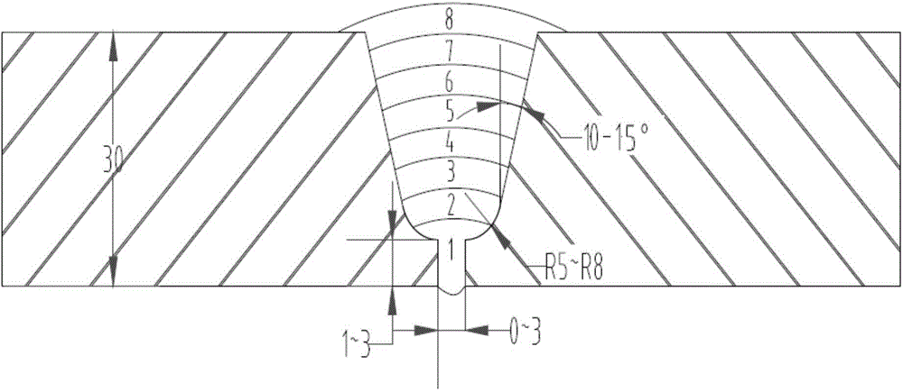
[0035] Refer to attached figure 2

[0036] The stainless steel sheet material is 022Cr17Ni12Mo2, the thickness is 30mm, the welding wire type is ER316L, and the U-shaped groove is adopted. The following steps and process parameters are used to make:

[0037] 1) Process a bevel at the stainless steel joint by machining, and use acetone to remove oil and harmful impurities within 20 mm of the surface of the bevel and the base material on both sides of the bevel, and make the welded part and the surrounding area reveal metallic luster. Dry the bevel and surrounding area without residual moisture.

[0038] 2) Selection of weld groove shape: U-shaped groove with groove angle of 30°, blunt edge thickness of 2mm, and eliminate burrs.

[0039] 3) The gap between base metal groups is 2mm, and the misalignment of the inner surface of the base metal is less than 2mm.

[0040] 4) Sealing measures are adopted on the back of the weld, and only the air inlet and outlet are opened. The b...


PUM

PropertyMeasurementUnit
thicknessaaaaaaaaaa
thicknessaaaaaaaaaa
thicknessaaaaaaaaaa

Abstract

The invention relates to an austenitic stainless steel welding method. The mode that high-purity nitrogen is blown to the back of a welding joint takes the place of the mode that when argon arc welding is performed in the prior art, the back of the welding joint is filled with argon, and backing weld of austenitic stainless steel can be completed. For a base material with the thickness larger than 20 mm, after the backing weld ends, other welding modes, such as electric arc welding, are adopted for completing later welding work. According to the method, due to the fact that the operating instruction is seriously controlled, the argon arc welding effect adopting full-argon shield can be obtained finally. Because the source of nitrogen is wide and the nitrogen is free of pollution, easy to prepare and low in cost, when the method is adopted for welding the austenitic stainless steel, and welding cost can be effectively saved.

Description

technical field [0001] The invention relates to a welding process, in particular to an argon arc welding process of austenitic stainless steel. Background technique [0002] Austenitic stainless steel refers to stainless steel with austenitic structure at room temperature. When the steel contains about 18% Cr, 8% to 10% Ni, and about 0.1% C, it has a stable austenite structure. Austenitic chromium-nickel stainless steel includes the famous 18Cr-8Ni steel and the high Cr-Ni series steel developed on the basis of increasing Cr and Ni content and adding Mo, Cu, Si, Nb, Ti and other elements. Austenitic stainless steel is non-magnetic and has high toughness and plasticity, but its strength is low. It is impossible to strengthen it through phase transformation. It can only be strengthened by cold working. If S, Ca, Se, Te and other elements are added, it has good properties. Machinability. [0003] Argon is an inert gas with a single-atom structure. It does not chemically inte...

Claims


Application Information

Patent Timeline
Patent Type & Authority Applications(China)
IPC IPC(8): B23K9/16B23K9/02B23K9/235B23K33/00B23K103/04
CPCB23K9/173B23K9/02B23K9/235B23K33/004B23K2103/04
Inventor 陆东跃林锋汤明珠袁俊峰朱钰
Owner ZHEJIANG BOFAN POWER EQUIP CORP
Learn More