A method for preparing an optical fiber preform and drawing an optical fiber

An optical fiber preform and preform technology, which is applied to glass manufacturing equipment, manufacturing tools, etc., can solve the problem of high process cost, maintenance cost and environmental protection treatment cost, high complexity of preform mainstream technology, and strict requirements for equipment, process and environmental protection. and other problems, to achieve the effect of reducing comprehensive production costs, excellent product performance, and obvious cost advantages

Active Publication Date: 2017-11-24
久智光电子材料科技有限公司 +1
View PDF5 Cites 0 Cited by
  • Summary
  • Abstract
  • Description
  • Claims
  • Application Information

AI Technical Summary

Problems solved by technology

OVD and VAD technologies need to use SiCl on the periphery of the mandrel 4 Chemical vapor deposition as the main raw material to form SOOT body, and then in Cl 2 dehydration under the same conditions and generate a large amount of HCl harmful gas at the same time, and then complete sintering and vitrification under the protection of helium. Each of the above steps needs to be carried out in a separate process device. The equipment, process and environmental protection requirements are very strict, and the process cost, maintenance cost and environmental protection treatment cost are extremely high
[0003] There have been many reports on the methods of drawing optical fibers from preforms. Although the process details are different, it is generally necessary to disassemble and cool the prepared preforms, transfer them to the optical fiber drawing tower device for reassembly and fixation, and reheat them. In order to complete the processes of melting and wire drawing, the process is complex and the control of process parameters is difficult

Method used


Image

  • A method for preparing an optical fiber preform and drawing an optical fiber
  • A method for preparing an optical fiber preform and drawing an optical fiber
  • A method for preparing an optical fiber preform and drawing an optical fiber

Examples


example 1

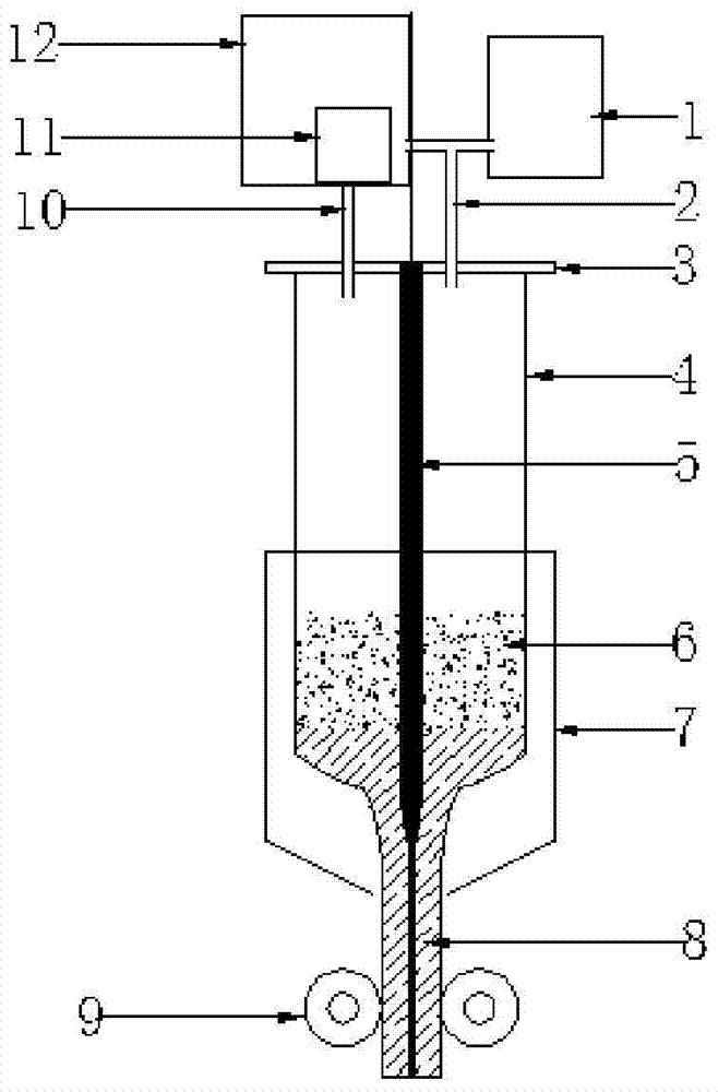
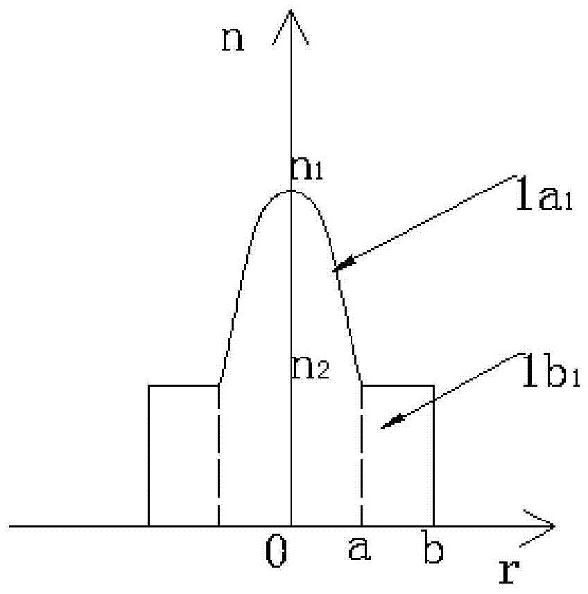
[0040] Example 1: Using an electric heating furnace device as a heat source, arranging a core containing SiO in a quartz tube 2 Department of glass rod (cross-sectional structure such as figure 2 , 1a 1 —Multimode core layer, n 1 —Refractive index of the multimode core layer, 1b 1 — multimode optical cladding, n 2—refractive index of the multimode optical cladding), length 1000mm, diameter 50mm, after welding the rod is assembled and fixed vertically into the quartz tube and kept coaxial, the height of the quartz tube is 1200mm, diameter 120mm, wall thickness 5mm, installed on the top It is best to have a high temperature resistant sealing device with a quartz sand discharge port and a vacuum port, close the quartz sand discharge port, and vacuum to 4mbar.

[0041] Start the quartz sand automatic feeding system, fill the 100 mesh to 300 mesh quartz sand material with a purity of 99.999% or more into the aforementioned quartz tube container at a predetermined height of 200...

example 2

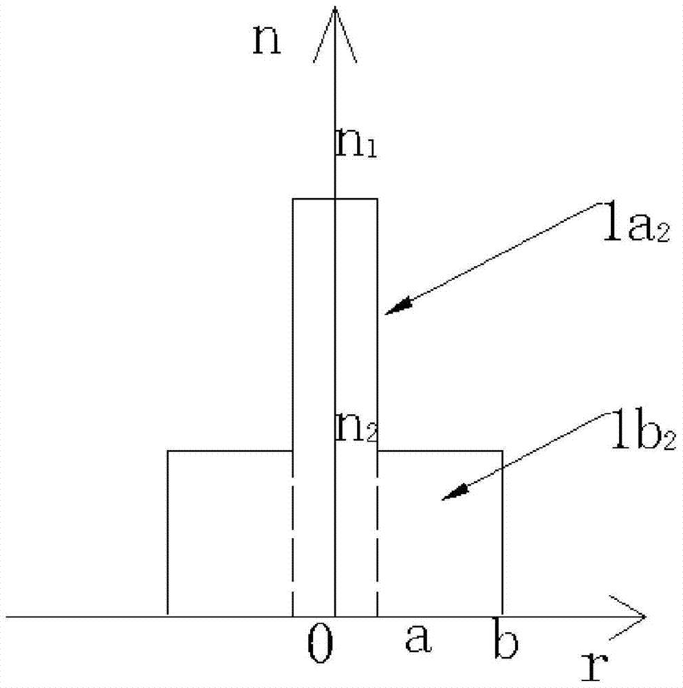
[0044] Example 2: Using a heating furnace device as a heat source, arranging a core containing SiO2 in a quartz tube container 2 Department of glass rod (cross-sectional structure such as image 3 , 1a 2 —Single-mode core layer, n 1 —Refractive index of the single-mode core layer, 1b 2 — single-mode optical cladding, n 2 —refractive index of single-mode optical cladding), length 1500mm, diameter 40mm, after welding the rods are assembled and fixed vertically into the quartz tube and kept coaxial, the height of the quartz tube is 1700mm, diameter 210mm, wall thickness 5mm, installed on the top It is best to have a high temperature resistant sealing device with a quartz sand discharge port and a vacuum port, close the quartz sand discharge port, and vacuum to 9mbar.

[0045] Start the quartz sand automatic feeding system, fill the 100 mesh to 300 mesh quartz sand material with a purity of 99.999% or more into the aforementioned quartz tube container at a predetermined height...

example 3

[0048] Example 3: Using the heating furnace device as the heat source, disposing SiO for the core in the quartz tube container 2 Glass rod (cross-sectional structure such as Figure 4 , 1a 3 —Pure SiO 2 core layer, n 1 —Pure SiO 2 Refractive index of the core, 1b 3 — SiO doped with F 2 Optical cladding, n 2 — SiO doped with F 2 Refractive index of the optical cladding), length 1500mm, diameter 10mm, after welding the rods are assembled and fixed vertically into the quartz tube and kept coaxial, the height of the quartz tube is 700mm, the diameter is 170mm, and the wall thickness is 5mm. The high-temperature-resistant vacuum plug of the quartz sand discharge port and the vacuum port, close the quartz sand discharge port, and vacuum to 7mbar.

[0049] Start the quartz sand automatic feeding system, fill the 100 mesh-300 mesh doped F element quartz sand mixture into the aforementioned quartz tube container at a predetermined height of 300mm, and start heating and melting....


PUM

PropertyMeasurementUnit
diameteraaaaaaaaaa
lengthaaaaaaaaaa
diameteraaaaaaaaaa

Abstract

The invention relates to a method for preparing an optical fiber preform rod and drawing an optical fiber. It uses a heating furnace device as a heat source, and a quartz crucible container containing SiO 2 A glass-based rod is filled with high-purity quartz sand or a mixture of quartz sand doped with F or B and other elements into the aforementioned container, melted at high temperature and drawn out of the SiO core containing the core. 2 The outer periphery of the glass rod has SiO 2 Optical fiber preforms with cladding or quartz sand mixture outer cladding doped with elements such as F or B can also be directly drawn out of optical fiber products by adjusting the drawing process parameters.

Description

technical field [0001] The invention relates to a method for preparing an optical fiber preform rod and drawing an optical fiber. Background technique [0002] At present, the production of optical fiber preforms mostly adopts a two-step method, that is, to manufacture the core rod first, and then use different technologies to manufacture the outer cladding outside the core rod. Outer cladding technology mainly includes OVD, VAD and other process methods. OVD and VAD technology need to use SiCl on the periphery of the mandrel 4 Chemical vapor deposition as the main raw material to form SOOT body, and then in Cl 2 dehydration under the same conditions and generate a large amount of HCl harmful gas at the same time, and then complete sintering and vitrification under the protection of helium. Each of the above steps needs to be carried out in a separate process device. The equipment, process and environmental protection requirements are very strict, and the process cost, ma...

Claims


Application Information

Patent Timeline
Patent Type & Authority Patents(China)
IPC IPC(8): C03B37/012C03B37/025
Inventor 张锦秦卫光谷巨明刘晓光孙丽丽王春玲李文彦张春林
Owner 久智光电子材料科技有限公司
Why Eureka
Try Eureka