
Pyrolysis and gasification device and technology

A technology of pyrolysis gasification and process, applied in the direction of granular/powdered fuel gasification, petroleum industry, coking carbonaceous materials, etc., can solve the problems of generating too much tar, reducing utilization efficiency, secondary pollution, etc., and achieve carbon reduction chain length, achieve material balance, and improve the effect of oil quality

Active Publication Date: 2015-07-22
TAIYUAN UNIV OF TECH
View PDF4 Cites 27 Cited by
  • Summary
  • Abstract
  • Description
  • Claims
  • Application Information

AI Technical Summary

Problems solved by technology

However, this process has the following disadvantages: First, due to the small particle size of the high-temperature circulating ash, there is a high dust content in the pyrolysis gas, which is likely to cause problems such as pipeline blockage and difficult separation of dust and tar. The calorific value is low, the density is low, and the heat transfer efficiency is not high; secondly, the pyrolysis device used in this process is a bubbling fluidized bed pyrolyzer. There are significant differences in the reaction stages, which reduces the selectivity and pyrolysis efficiency of the target product tar, which is not conducive to the formation of high-quality tar
Therefore, biomass pyrolysis and gasification, as a technical means for large-scale utilization of biomass energy, have attracted more and more attention. However, the energy density of biomass is low. It is not easy to control, the equipment is easy to corrode, and generates a lot of tar, which not only reduces its utilization efficiency, but also causes secondary pollution, which limits the scale of separate pyrolysis or gasification

Method used


Image

  • Pyrolysis and gasification device and technology

Examples


Embodiment

[0030] First, the pyrolysis gasification device is described:

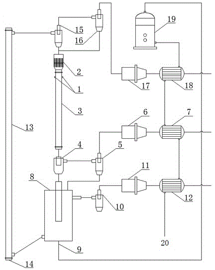
[0031] Such as figure 1 Shown, a kind of pyrolysis gasification device is characterized in that, comprises three main reactors of burner, pyrolyzer, gasifier, and described pyrolyzer is down-bed rapid pyrolyzer 3, and gasifier is Bubbling bed gasifier 8, the burner is an ascending bed oxidation burner 13;

[0032] The upper part of the down-bed fast pyrolyzer 3 is provided with a raw material inlet 1, above the raw material inlet 1 is a distributor 2, and the bottom of the down-bed fast pyrolyzer 3 is connected to the inertial separator 4; the side of the inertial separator 4 is connected to the first cyclone separator in turn 5. The first bag filter 6, the first cooler 7; the bottom of the inertia separator 4 is connected to the bubbling bed gasifier 8; the upper end of the bubbling bed gasifier 8 is connected to the first cyclone separator 5, and a water Steam and oxygen inlet 9, the upper side of the bubbling...


PUM


Abstract

The invention discloses a pyrolysis and gasification device and technology. The device comprises three main reactors, namely, an uplink bed oxidation combustor, a downlink bed rapid pyrolyzer and a bubbling bed gasifier. Feed coal or a mixture of coal and biomass is added from the upper part of the pyrolyzer, is rapidly heated by high-temperature circulating semicoke from the combustor and has a catalytic pyrolysis reaction, and semicoke, tar and gas are produced; through rapid separation, fresh semicoke produced in the pyrolyzer and the high-temperature circulating semicoke are sent into the gasifier to have a gasification reaction with a gasification agent; the semicoke which is not gasified is continuously sent into the combustor to be partially oxidized and combusted under the action of oxygen, so that a large quantity of high-temperature circulating semicoke is obtained. The device and the technology have the advantages that a combustion-pyrolysis-gasification process in graded utilization of raw materials is coupled, co-production of high-quality tar, gas and synthesis gas is realized by the aid of the catalytic activity and the heat-carrying capability of the semicoke, and the economic benefit and the social benefit are high.

Description

technical field [0001] The invention relates to a pyrolysis gasification device and process, especially a three-tower high-throughput semi-coke circulating fluidized bed coal or a mixture of coal and biomass heat based on semi-coke's catalytic activity and self-heating capacity Degasification process. The invention belongs to the field of thermochemical conversion graded utilization of low-rank coal or mixture of coal and biomass coupled with pyrolysis-gasification-combustion. Background technique [0002] Coal is the main energy source in my country, and it will still play a dominant role in my country's energy structure for a long time to come. Among them, low-rank coal reserves represented by lignite and low-metamorphic bituminous coal account for 55% of the total coal resources. above. As high-metamorphic coal types become less and less, the optimal utilization of low-rank coals becomes increasingly important. However, low-rank coal has low degree of coalification, hig...

Claims


Application Information

Patent Timeline
IPC IPC(8): C10B55/06C10B49/18C10J3/56C10J3/72C10J3/84C10G1/00
CPCC10B49/16C10B53/02C10B53/04C10J3/66C10J3/84Y02E50/10
Inventor 郝晓刚王俊丽连文豪杨景轩李鹏张忠林王伊楠黄伟
Owner TAIYUAN UNIV OF TECH
Learn More