
Filtering separation device for biomass pyrolytic heavy oil sludge and separation process thereof

A biomass pyrolysis, filtration and separation technology is applied in the field of filtration and separation devices and separation processes for biomass pyrolysis heavy oil sludge, which can solve the problems of increasing the viscosity and specific gravity of heavy oil, backward devices, and late start, and improve the oil yield. , save energy, avoid the effect of blockage

Active Publication Date: 2015-07-22
广饶县泽润环保科技有限公司
View PDF4 Cites 0 Cited by
  • Summary
  • Abstract
  • Description
  • Claims
  • Application Information

AI Technical Summary

Problems solved by technology

At present, my country's biomass pyrolysis fuel oil technology started late, and there are shortcomings such as backward equipment, immature technology, and low pyrolysis yield, so a certain production scale has not been formed.
[0003] Because the pyrolysis gas after biomass pyrolysis passes through the condensation of different temperature gradients in the fractionation tower, different products are produced, and the general pyrolysis device has incomplete pyrolysis and incomplete separation, so some lignin, heat Carriers, biomass semi-coke and other solid components enter the fractionation tower and exist in the heavy oil after quenching, which increases the viscosity and specific gravity of the heavy oil, making some oil products a slightly fluid sludge. If the viscous oil is not discharged in time emulsification, it will cause the fractionation column to return to the tower circulation pipeline and equipment blockage and shut down

Method used


Image

  • Filtering separation device for biomass pyrolytic heavy oil sludge and separation process thereof
  • Filtering separation device for biomass pyrolytic heavy oil sludge and separation process thereof
  • Filtering separation device for biomass pyrolytic heavy oil sludge and separation process thereof

Examples


Embodiment Construction

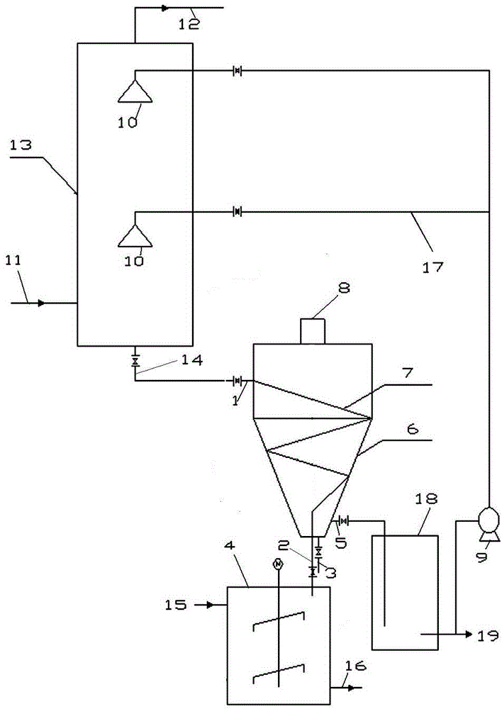
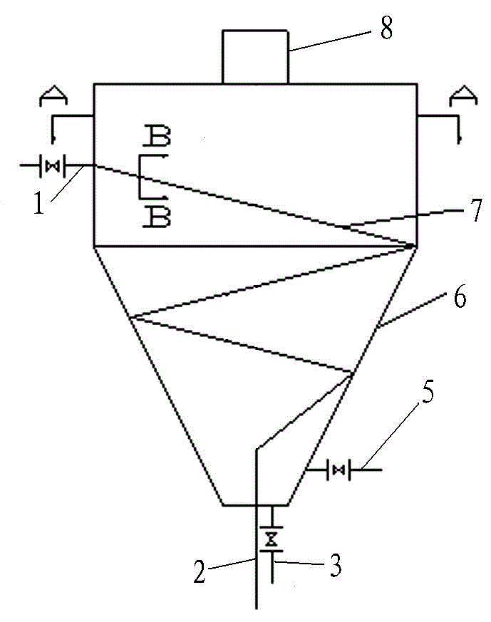
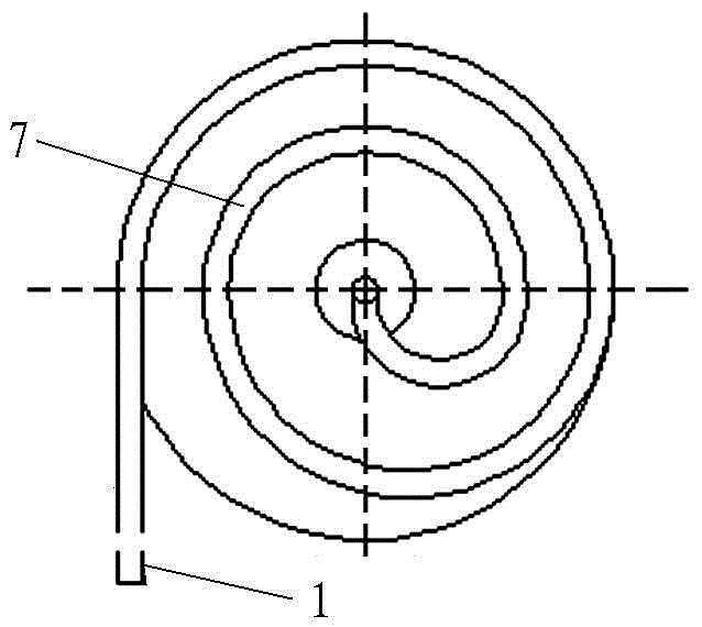
[0024] see Figure 1-4 , a filtration and separation device for biomass pyrolysis heavy oil sludge, mainly including a fractionation tower 13 connected by pipelines, a vertical centrifugal filter separator 6, an emulsification reaction kettle 4 and a heavy oil intermediate tank 18; the vertical centrifugal filter separator 6 is A hollow cylinder formed by connecting the upper cylinder and the lower cone; the hollow cylinder is provided with an insulation layer (preferably an insulation cotton layer with a thickness of more than 15 mm) on the outside of the hollow cylinder, and a heavy oil inlet 1 on the upper part. The continuous spiral filter channel 7 has a sludge outlet 2 at the bottom, and the heavy oil inlet 1 is connected to the upper inlet of the filter channel 7, and the sludge outlet 2 is connected to the lower end outlet of the filter channel 7; the inner wall of the vertical centrifugal filter separator 6 is from top to bottom A plurality of angle irons 20 are welde...


PUM


Abstract

The invention discloses a filtering separation device for biomass pyrolytic heavy oil sludge and a separation process thereof. The separation process comprises the following steps: discharging the mixture of the heavy oil and the sludge from the bottom part of a fractionating tower at a high temperature, directly entering into a centrifuge filtering separation device from the upper side position along the inner wall tangential direction, filtering the heavy oil from the filtering nets on the side part and the upper part through a filtering channel, and discharging from the lower liquid oil outlet, and pumping into the fractionating tower to spray and circulate; and because the sludge is heavier than the heavy oil, discharging the sludge from the bottom part of a separator along the filtering channel and emulsifying. The process has the following advantages that (1) the continuous separation of the sludge and the liquid heavy oil is realized, the sludge is emulsified and cannot be polymerized into a solid so that the oil extraction rate of the liquid oil is increased; (2) the separated heavy oil is discharged through the sediments at bottom part of the separator and the bottom part of an intermediate tank so that the returned heavy oil does not contain excess impurities and the blockage of the pipe and the nozzle is avoided; and (3) the separation of the high-temperature sludge and the heavy oil is realized without an external force and the energy is saved.

Description

technical field [0001] The invention belongs to the field of biomass new energy, and in particular relates to a filtration and separation device and separation process for biomass pyrolysis heavy oil sludge. Background technique [0002] With the rapid development of society, the development of primary energy has been exhausted day by day, and biomass as a secondary energy has been paid more and more attention by people. Choosing new renewable energy sources and reducing environmental pollution has become the main goal pursued by people. At present, my country's biomass pyrolysis fuel oil technology started late, and there are shortcomings such as backward equipment, immature technology, and low pyrolysis yield, so a certain production scale has not been formed. [0003] Because the pyrolysis gas after biomass pyrolysis passes through the condensation of different temperature gradients in the fractionation tower, different products are produced, and the general pyrolysis de...

Claims


Application Information

Patent Timeline
IPC IPC(8): C10G53/02
Inventor 李杰侯海建
Owner 广饶县泽润环保科技有限公司
Learn More