Venture reactor used for treatment of acidic gas

A reactor and acid gas technology, which is applied in the purification of acid gas and the field of acid gas reactors, can solve the problems of inability to produce valuable fuming sulfuric acid, the production cycle cannot be guaranteed, and the device cannot operate normally, so as to prevent excessive evaporation and ensure Safe operation and easy installation

Active Publication Date: 2015-08-12
CHINA PETROLEUM & CHEM CORP +1
View PDF8 Cites 5 Cited by
  • Summary
  • Abstract
  • Description
  • Claims
  • Application Information

AI Technical Summary

Problems solved by technology

This process can only produce 98% industrial sulfuric acid, but cannot produce oleum with higher value. At the same time, due to the difficulty in the transportation and storage of sulfuric acid, the stable market demand near the refinery is an important factor limiting its development.
[0005] CN1836767A discloses a treatment method for sour gas in refineries, utilizing sour gas as the fuel for shaft kilns in cement plants, when the sour gas is burned in the kiln, the H 2 S component reacts chemically with cement material to generate CaSO 4 , other harmful components are also sintered and transformed, which fundamentally solves the problem of acid gas treatment. At the same time, acid gas is used as a gas fuel to make the cement plant energy-saving fuel and achieve the dual purposes of environmental protection and fuel resolution. However, this The method has certain limitations and is not easy to promote
However, there are still problems such as pipeline crystallization blockage and low product quality.
There are also manufacturers who have built an experimental device for producing sodium hydrosulfide with hydrogen sulfide in acid gas using a bubble column reactor. The production process has been greatly improved, but the production cycle cannot be guaranteed. Sodium carbonate is generated, causing the device to fail to operate normally and the product quality is not high

Method used


Image

  • Venture reactor used for treatment of acidic gas

Examples


Embodiment Construction

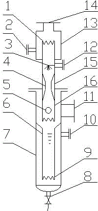
[0024] Such as figure 1 As shown, the present invention provides a kind of Venturi acid gas reactor, and described reactor is divided into three sections from top to bottom, and upper section is liquid phase storage tank 13, and middle section is straight cylinder reaction tube 15, and from top to bottom is inlet and outlet successively. Feed section 1, contraction section 4, throat section 17, expansion section 18 and discharge section 16, the lower section is a liquid-sealed cylinder with a lower end discharge opening 8, and the liquid-sealed cylinder includes a liquid-sealed inner cylinder 6 and a liquid-sealed outer cylinder 7; The upper part of the section forms a set structure with the liquid phase storage tank, and the lower part of the discharge section forms a set structure with the liquid seal cylinder. The upper end of the liquid phase storage tank is provided with a gas phase inlet 14, and the side wall of the liquid phase storage tank is provided with a circulating...


PUM


Abstract

The invention discloses an acidic gas reactor. The reactor is divided into three sections from top to bottom. An upper section is a liquid phase storage tank; a middle section is a straight-tube reaction tube and successively comprises, from top to bottom, a feed segment, a contraction segment, a throat pipe segment, an expansion segment and a discharge segment; the lower section is a liquid seal drum with an emptying opening at the lower end, and the liquid seal drum comprises an inner liquid seal drum and an outer liquid seal drum; the upper part of the feed segment and the liquid phase storage tank form a sleeve connection structure and the lower part of the feed segment and the liquid seal drum form a sleeve connection structure; the liquid phase storage tank is provided with a gas phase inlet, the position of the gas phase inlet is higher than an inlet at the upper end of the feed segment, and the sidewall of the liquid phase storage tank is provided with a circulation solution inlet; the tube wall of the straight-tube reaction tube is provided with an absorption liquid inlet which is located at the upper part of a throat pipe; and the inner liquid seal drum and the outer liquid seal drum are in a sleeve connection structure, the inner liquid seal drum is located at the lower part of the discharge segment, and the outer wall of the outer liquid seal drum is provided with a gas phase outlet and a liquid phase outlet. Compared with conventional reactors, the reactor provided by the invention has the advantages of high reaction efficiency, small equipment scale, uneasy obstruction and applicability to absorption reaction of acidic gas and alkali lye.

Description

technical field [0001] The invention relates to an acid gas reactor, which is suitable for the field of acid gas purification, and is especially suitable for a treatment method and device for the purification of sulfur-containing hydrogen compounds and other acid gases and the recycling of pollutants. Background technique [0002] Refinery acid gas mainly comes from sour water stripping, circulating hydrogen desulfurization, dry gas desulfurization and other devices. The acid gas mainly contains H 2 S, CO 2 . At present, the acid gas in most small refineries basically adopts the treatment method of post-combustion emission. On the one hand, this method causes a waste of resources, on the other hand, it brings huge pressure to environmental protection and affects the development space of enterprises. In order to protect the environment and ensure the full utilization of resources, it is imperative to recycle the acid gas from small refineries. [0003] With the further in...

Claims


Application Information

Patent Timeline
Patent Type & Authority Applications(China)
IPC IPC(8): B01D53/40B01D53/52B01D53/78
Inventor 陈新彭德强王璐瑶陈建兵孟凡飞王岩王阳峰孟凡忠
Owner CHINA PETROLEUM & CHEM CORP
Why Eureka
Try Eureka