Steel-super high performance concrete composite beam based on ribbed plate type bridge deck and construction method

An ultra-high performance, concrete technology, applied in bridges, bridge parts, bridge materials, etc., can solve problems such as weakening the effect of pre-compression stress of concrete slabs, adverse effects on durability, increasing the burden on steel beams, etc., to achieve good economic Benefit, avoid negative bending moment zone disease, reduce the effect of structure self-weight

Inactive Publication Date: 2015-08-12
FUZHOU UNIV
View PDF4 Cites 37 Cited by
  • Summary
  • Abstract
  • Description
  • Claims
  • Application Information

AI Technical Summary

Problems solved by technology

When the strong reinforcement method is used alone, it is only suitable for the construction of small and medium-span bridges, because of its long-term work with cracks, it has an adverse effect on durability
The method of applying precompressive stress inevitably also imposes additional stress on the shear connectors, which not only increases the burden on the steel beam, but also weakens the effect of precompressive stress on the concrete slab; The additional stress on the shear connectors is reduced, but the bonding strength between the post-cast belt and the precast concrete connection interface is poor, and there are weak links or corrosion channels in the composite beam at the connection interface of different materials.

Method used


Image

  • Steel-super high performance concrete composite beam based on ribbed plate type bridge deck and construction method
  • Steel-super high performance concrete composite beam based on ribbed plate type bridge deck and construction method
  • Steel-super high performance concrete composite beam based on ribbed plate type bridge deck and construction method

Examples


Embodiment Construction

[0025] In order to make the above-mentioned features and advantages of the present invention more comprehensible, the following specific embodiments are described in detail with reference to the accompanying drawings.

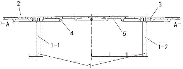
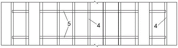
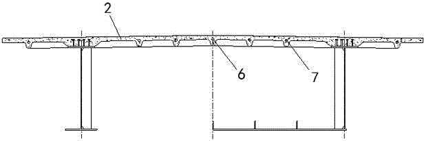
[0026] Such as Figure 1~3 As shown, a steel-ultra-high-performance concrete composite beam based on a ribbed bridge deck includes a steel girder 1 on which an ultra-high-performance concrete bridge deck 2 is placed, and the ultra-high-performance concrete bridge deck 2 The steel girder 1 is fixed together by the shear connector 3, and the ultra-high performance concrete bridge deck 2 is provided with a reinforcement mesh composed of steel bars criss-crossing. At least one of them is a rib structure to form a ribbed ultra-high performance concrete bridge deck 2 .

[0027] Wherein, the ultra-high-performance concrete bridge deck 2 is poured from ultra-high-performance concrete, and the ultra-high-performance concrete means that the components contain steel fibe...


PUM


Abstract

The invention discloses a steel-super high performance concrete composite beam based on a ribbed plate type bridge deck and a construction method. The construction method includes the following steps that step1, steel beams are machined, manufactured and installed; step2, shearing force connecting parts are welded; step3, the super high performance concrete bridge deck is constructed; step4, a guardrail or an anti-collision wall is constructed; step5, bridge deck pavement is constructed, wherein the super high performance concrete bridge deck and the steel beams are fixed through the shearing force connecting parts, the cross section or/and the longitudinal section of the super high performance concrete bridge deck is/are of a ribbed plate structure, and pre-stressed reinforcements can be arranged on a longitudinal rib region or/and a transverse rib region. The composite beam is reasonable in stress, high in strength and capable of substantially reducing the structure dead weight, effectively avoiding defects at a hogging moment region of a composite continuous beam and bringing tensile strength, compressive strength and high durability of super high performance concrete into full play; the composite beam has the advantages of being small in building height, high in rigidity, small in dead weight, good in durability, crack resistance and fatigue resistance and the like, and has great practical value and good economic benefits.

Description

technical field [0001] The invention relates to the technical field of civil engineering, in particular to a steel-ultra-high-performance concrete composite beam based on a ribbed bridge deck and a construction method thereof. Background technique [0002] Composite beam structures are widely used in the fields of roads, bridges and construction due to their advantages of reasonable material utilization, economy, and convenient construction. However, the concrete in the negative bending zone of composite continuous beams is prone to cracking under tension, resulting in poor durability of composite beams. In order to solve this problem, two methods are currently used in the design: one method is to allow the concrete slab in the structure to crack, but limit the width of the crack, usually to increase the reinforcement ratio of the structure so that the concrete slab meets the requirements under normal use. The limit of the crack width, that is, the strong reinforcement meth...

Claims


Application Information

Patent Timeline
Patent Type & Authority Applications(China)
IPC IPC(8): E01D19/00E01D19/12E01D21/00E01D101/28
Inventor 赵秋陈宝春
Owner FUZHOU UNIV
Why Eureka
Try Eureka