
Ku-band circularly-polarized cone beam antenna

A circular polarization and antenna technology, applied in the fields of anti-jamming, satellite communication, and reconnaissance radar, can solve the problems of low gain, narrow adaptive frequency band, and poor shock resistance, and achieve the effects of reducing processing costs, reducing ohmic loss, and reliable mechanical properties

Active Publication Date: 2015-08-12
江苏拓元科技发展有限公司
View PDF5 Cites 4 Cited by
  • Summary
  • Abstract
  • Description
  • Claims
  • Application Information

AI Technical Summary

Problems solved by technology

[0016] These implementation methods generally have disadvantages such as complex feed network, low gain, poor roundness, complex structure, poor shock resistance, and narrow frequency range.

Method used


Image

  • Ku-band circularly-polarized cone beam antenna
  • Ku-band circularly-polarized cone beam antenna
  • Ku-band circularly-polarized cone beam antenna

Examples


Embodiment 1

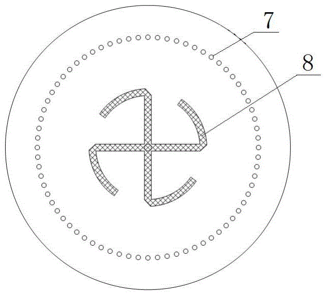
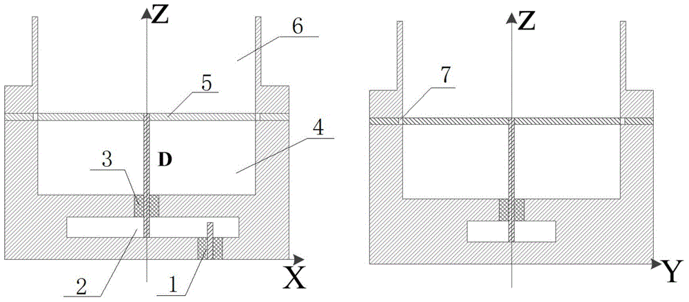
[0038] Example 1:The sectional view of the overall structure of the antenna shown in Figure 1(a) and the feeding structure diagram of the printed hook of the antenna shown in Figure 1(b), the Ku-band circularly polarized cone-beam antenna according to the present invention includes an open circular waveguide 6 and a large coaxial waveguide 4, a dielectric plate 5 with a hook structure 8 sandwiched between them, and a small coaxial waveguide 3, a rectangular waveguide 2 and an SMA connector 1; wherein the open circular waveguide structure 6, the dielectric plate 5 and The large coaxial waveguide 4 is fixed together by screws to form the main radiation part of the antenna; the open circular waveguide 6 and the large coaxial waveguide 4 are both strictly rotationally symmetrical structures; the hook structure on the dielectric plate 5 is printed on its upper layer and is consistent with Datong The inner conductors in the axial waveguide 4 are connected; the radius of the inner c...


PUM


Abstract

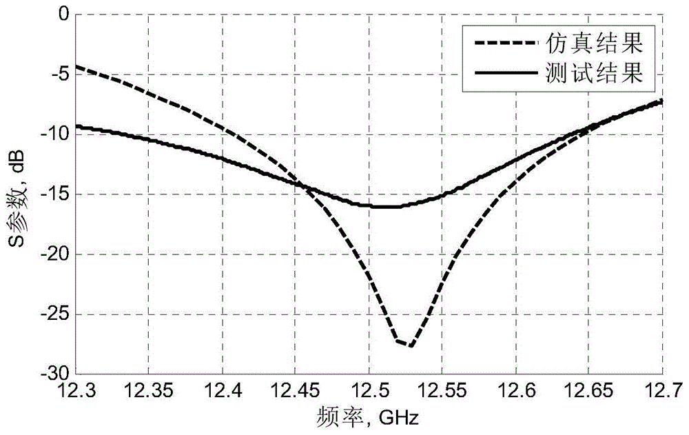
The invention discloses a Ku-band circularly-polarized cone beam antenna comprising an open circular waveguide, a large coaxial waveguide, a small coaxial waveguide, a rectangular waveguide, an SMA connector, and a dielectric plate clamped between the open circular waveguide and the large coaxial waveguide and printed with a hook structure. The printed hook structure and the large coaxial waveguide simultaneously excite two radially-symmetric circular waveguide modes (TM01 and TE01) of which the spatial positions are perpendicular to each other, the phase difference is 90 degrees and the amplitudes are the same, thus generating a circularly-polarized far-field cone radiation pattern. Conversion coaxial to the rectangular waveguide is formed twice between the large coaxial waveguide and the SMA connector to complete feeding of the whole antenna. Under the condition of maintaining the compact structure of the circularly-polarized cone beam antenna, good circularly polarized radiation characteristic and impedance matching characteristic are achieved at the resonant frequency of 12.5 GHz.

Description

technical field [0001] The invention belongs to the technical fields of satellite communication, reconnaissance radar, anti-jamming and the like, and in particular relates to a Ku-band circularly polarized conical beam antenna suitable for target tracking and detection. Background technique [0002] The field of circularly polarized wave at every point in space is a constant-amplitude rotating field, and the direction of rotation can be divided into left-handed and right-handed. A left-handed circularly polarized antenna can only radiate or receive left-handed circularly polarized waves, and a right-handed circularly polarized antenna can only radiate or receive right-handed circularly polarized waves. The reflection characteristics of different objects to electromagnetic waves have a lot to do with the polarization state of the waves, and circularly polarized waves have some unique properties. Therefore, in modern equipment such as satellite communications, jamming radars, ...

Claims


Application Information

Patent Timeline
Patent Type & Authority Applications(China)
IPC IPC(8): H01Q1/38H01Q23/00H01Q1/50
Inventor 方大纲
Owner 江苏拓元科技发展有限公司
Learn More