Electrolysis device based on electrowetting-on-dielectric layer principle, and manufacturing method thereof

A dielectric layer and electrowetting technology, applied in the direction of electrolytic components, electrolytic process, etc., can solve the problems of strict process conditions, low integration, single function, etc., achieve the effect of simplifying the chip structure, expanding the application range, and simplifying the manufacturing process

Inactive Publication Date: 2015-08-19
FUDAN UNIV
View PDF5 Cites 11 Cited by
  • Summary
  • Abstract
  • Description
  • Claims
  • Application Information

AI Technical Summary

Problems solved by technology

The electrowetting technology on the medium changes the wettability of the droplet on the surface of the medium by voltage to control the droplet. It has many advantages such as simple driving method, strong driving force, and high degree of automation, but it has disadvantages such as single function and low integration.
[0004] Electrolysis is a commonly used technology in many fields such as biology and chemistry, but most of the existing electrolysis methods have problems such as generation of bubbles, uneven distribution of electrolysis products, inaccurate control of the degree of electrolysis reaction, strict process conditions, and large amount of reagents. Limit its application in portable devices and lab-on-a-chip

Method used


Image

  • Electrolysis device based on electrowetting-on-dielectric layer principle, and manufacturing method thereof
  • Electrolysis device based on electrowetting-on-dielectric layer principle, and manufacturing method thereof

Examples


Embodiment Construction

[0030] The present invention will be further described below through specific embodiments in conjunction with the accompanying drawings. These embodiments are only used to illustrate the present invention, and are not intended to limit the protection scope of the present invention.

[0031] The electrolytic device based on the principle of electrowetting on the dielectric layer provided by the present invention is realized through electrode design and driving signal control, so it can be configured in various ways and can be configured in various digital microfluidic chips.

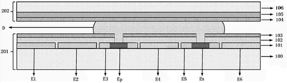
[0032] Schematic diagram (longitudinal sectional view) of the principle structure of the present invention such as figure 1 shown. On the insulating first substrate 100 are the driving electrodes E1-E6 and the electrolysis electrodes Ep and En of the present invention, wherein the electrolysis electrodes Ep and En are respectively embedded in the driving electrodes E3 and E5, but are electrically isolated...


PUM


Abstract

The invention discloses an electrolysis device based on an electrowetting-on-dielectric layer principle, and a manufacturing method thereof. The electrolysis device includes: a lower electrode plate formed by sequentially arranging a first substrate, an electrode layer, a dielectric layer and a first hydrophobic layer from bottom to top; and an upper electrode plate formed by sequentially arranging a second substrate, a grounding electrode and a second hydrophobic layer from top to bottom; liquid drops D to be electrolyzed are placed between the first hydrophobic layer and the second hydrophobic layer; the electrode layer includes a plurality of electrolysis electrodes and a plurality of driving electrodes, and adjacent electrodes are electrically isolated; and the electrolysis electrodes are embedded into the driving electrodes. Liquid drops containing a specific concentration of electrolysis products with different polarities can be obtained by controlling the electrolysis process and the liquid drop splitting process. The electrolysis device has the characteristics of novel design, simple control, high automation degree and high output precision, and greatly widens the application range of digital micro-fluidics, onsite rapid detection and other technologies.

Description

technical field [0001] The invention belongs to the technical field of digital microfluidics, and relates to a microfluidic technology based on the principle of electrowetting on a medium layer and an electrolysis process of a liquid, in particular to an electrolytic device based on the principle of electrowetting on a medium layer. Background technique [0002] Lab-on-a-chip can be simply defined as a miniaturized and integrated micro-electro-mechanical system that can complete various processes of biochemical processing and automatically complete traditional laboratory functions. Its goal is to integrate a complete analysis process on a single device, with high integration High-precision, high-precision, low-consumption, intelligent and other advantages, it has very good prospects in many fields such as biology and chemistry. [0003] As the power part of lab-on-a-chip, microfluidic technology plays an important role. The electrowetting technology on the medium changes th...

Claims


Application Information

Patent Timeline
Patent Type & Authority Applications(China)
IPC IPC(8): C25B15/02C25B15/08
Inventor 王伟曾智周嘉
Owner FUDAN UNIV
Why Eureka
Try Eureka